This is an old revision of the document!
Introduction
The objective of this project is to create a smart lock for doors using an ESP32 module acting as a asynchronous web server, which will receive HTTP GET commands from an android application.
Hardware
Main components:
Components for NPN transistor switch:
10k resistor
2k resistor
NPN 2n2222 transistor
Circuit Diagram
The pins of a relay module can be categorized in two groups: low-voltage group and high-voltage group. The low-voltage group is used to turn ON/OFF the relay (connecting/disconnecting the high-voltage circuit) [1]
Figure 1. Schematic for the connection between ESP32 and the Relay module
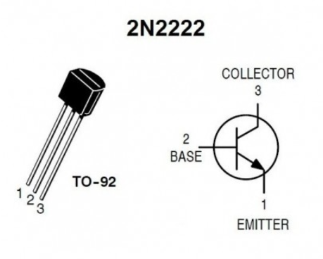
In order to understand the correlation between the schematic from Figure 1 and the breadboard implementation we need to understand what each pin of the transistor means. This can be seen in Figure 2.
Figure 2. NPN Transistor 2n2222
Now that we understand the transistor's connections we can implement the schematic from Figure 1. The breadboard implementation can be seen in Figure 3.
Figure 3. Breadboard implementation
The Electromagnetic Lock and the 12V Source will be connected to the 5V Relay on the 'Normally Closed' (NC) position.
How will the hardware work
The 3.3V GPIO pin from the ESP32 board will send a signal to the NPN switch to turn it ON/OFF, this will send the 5V from Vin pin of the ESP32 board to the IN pin of the 'low-voltage group' of the 5V Relay turning it ON/OFF (activating/deactivating the electromagnetic lock).
Software
Arduino
In order to send commands to ESP32 board using an Android application, we first need to setup the ESP32 as a web server and connect it to the WiFi. After the connection was resolved, in order to know where to send the request, the IP of the ESP32 will be retrieved using the WiFi.localIP() method. Because the scope of this project is to turn the relay ON/OFF (activating/deactivating the lock) the web server will respond at 2 HTTP_GET requests: http://192.168.0.128/relay/on and http://192.168.0.128/relay/off
#include "WiFi.h"
#include "ESPAsyncWebServer.h"

const char* ssid = "SSID";
const char* password =  "PASS";

AsyncWebServer server(80);
int RELAY_PIN = 27;

void setup() {
 pinMode(RELAY_PIN, OUTPUT);
 digitalWrite(RELAY_PIN, HIGH);
 Serial.begin(115200);
 WiFi.begin(ssid, password);

 while (WiFi.status() != WL_CONNECTED) {
   delay(1000);
   Serial.println("Connecting to WiFi..");
 }

 Serial.println(WiFi.localIP());

 server.on("/relay/off", HTTP_GET   , [](AsyncWebServerRequest *request){
   request->send(200, "text/plain", "ok");
   digitalWrite(RELAY_PIN, HIGH);
 });
  server.on("/relay/on", HTTP_GET, [](AsyncWebServerRequest *request){
   request->send(200, "text/plain","ok");
   digitalWrite(RELAY_PIN, LOW);
 });

 server.begin();
}
void loop(){}
Android
Sending HTTP requests
Accessing Camera
Connecting the Android application to ESP32.
Sending HTTP requests
Conclusions
Bibliography
[1] https://esp32io.com/tutorials/esp32-relay, ESP32 Relay, 24.01.22


