Retro Look Weather Station
author Dragulin Florin Catalin ACES 2022
I. Short Description
One network composed from one core station which will display ambient data on a VFD (Vacuum Fluorescent Display) and 1 or 2 more station powered by Li-Ion cell which will sample data from outside and inside the house. Key ambient parameters are temperature, humidity, atmospheric pressure and light illuminance.
II. Hardware
- 1. Core Station
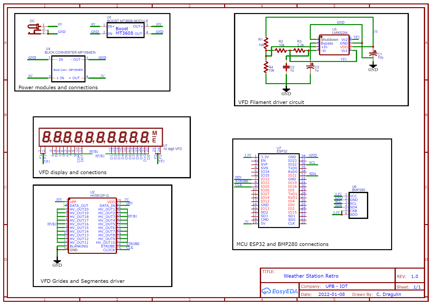
Core station will be powered from the outlet and will consists of an ESP32 as processor and WiFi interface, one VFD (SVE-11MS21 SAMSUNG 10digit) display which will show ambient information, data and time. Because it will be placed inside it’s has attached a BMP280 to measure temperature and atmospheric pressure.
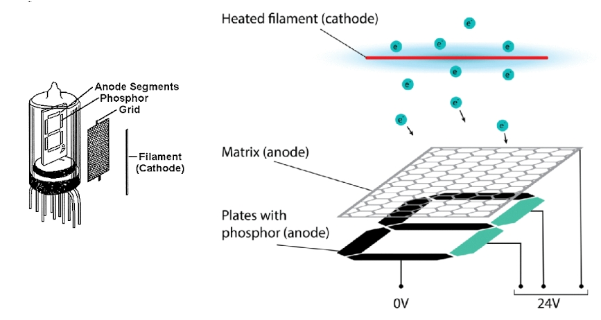
VFD or vacuum fluorescent display operates on the principle of cathodoluminescence, someway similar with old CRT but with much lower drive voltages. A tube has a phosphor-coted anode that is bombarded by electrons emitted from a filament which are accelerated via a mesh control grid. In a nutshell can be equivalent with an old triode, predecessor of transistors, used in radio and older electronic devices since 1907 when Lee De Forest invented them.
To drive the tube, 2 voltage levels are required, a smaller one to feed the filament, usually between 0.8V on a single 7segment tube to 4-5V for longer tubes with special characters or higher number of 7(16) segments, and a higher voltage for anode, typ. around 25-40V. For 10 digit tube we need a total of 10 pins to drive the grides, 7 pins for segments and other 3 for dot, comma and special character grid, summing 20 pins.
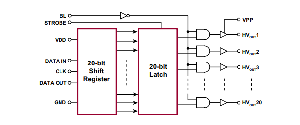
Due to limited amount on the ESP32 board, to drive those 20 pins I used a special IC which can handle higher voltages, Microchip HV5812, a serial 20-bit shift register with VDD = 4.5-5.5V for logic circuits and VPP = 20 – 80V for high voltage. Data-In, CLK and Strobe will be driven by ESP32. To obtain 30-32V from my 9V DC power I used a switch mode power supply (SMPS) with MT3608 IC to have a higher efficiency.
For filament voltage we can use either DC or AC. In small tubes DC has no downsize but in longer filaments such as my display, to get a uniform light intensity is mandatory to used AC. To make that possible I used another dedicated IC, LM9022 which produce a 25KHz square signal with an amplitude between 0.15V and 4.85V.
In the end, ESP32 dev board requires 4.3V or more due to the voltage drop on the AMS1117 (voltage regulator). To power it and the other devices a used another SMPS in this case to lower 9V DC to 5V, I used a buck circuit using MP1584EN IC. For monitoring side, a BMP180 is used to sample temperature and pressure inside. It’s having a I2C interface with 3.3V logic level, suitable for ESP32.
- 2. Slave station
It will be placed outside to sample temperature, humidity and pressure. To have communication with core station, I used the same microcontroller, ESP32 dev board. External parameters are capture using BMP280 with I2C interface at 3.3V logic level
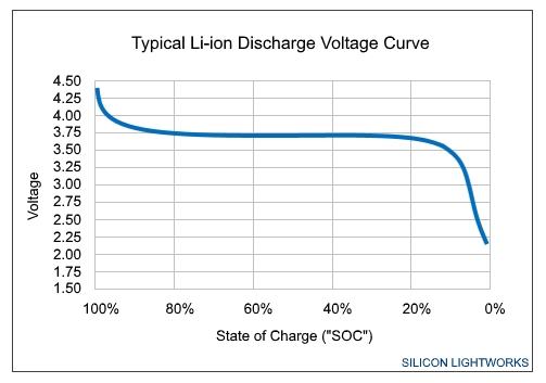
Outside outlets are not every time easy to get so a cordless station is needed. For that cheapest and fastest solution is to use a Li-Ion connected to 1W solar panel. Li-Ion cells have a maximum voltage at 4.2 – 4.3V when are at 100% state of charge (SOC), keep a steady voltage between 80% and 20% SOC, at 3.7V and then drop almost linearly to 2.3V.
Because the voltage regulator used in ESP32 dev board is not so good if we look at voltage drop, I can’t use it in combination with Li-Ion cell, so I replaced it with an LDL1117S33R which can supply a steady 3.3V even if the Li-Ion is below 20% SOC, so under 3.7V. To maximize battery life, slave station will wake up at a certain interval the samples, sends and go back to sleep.
III. Software
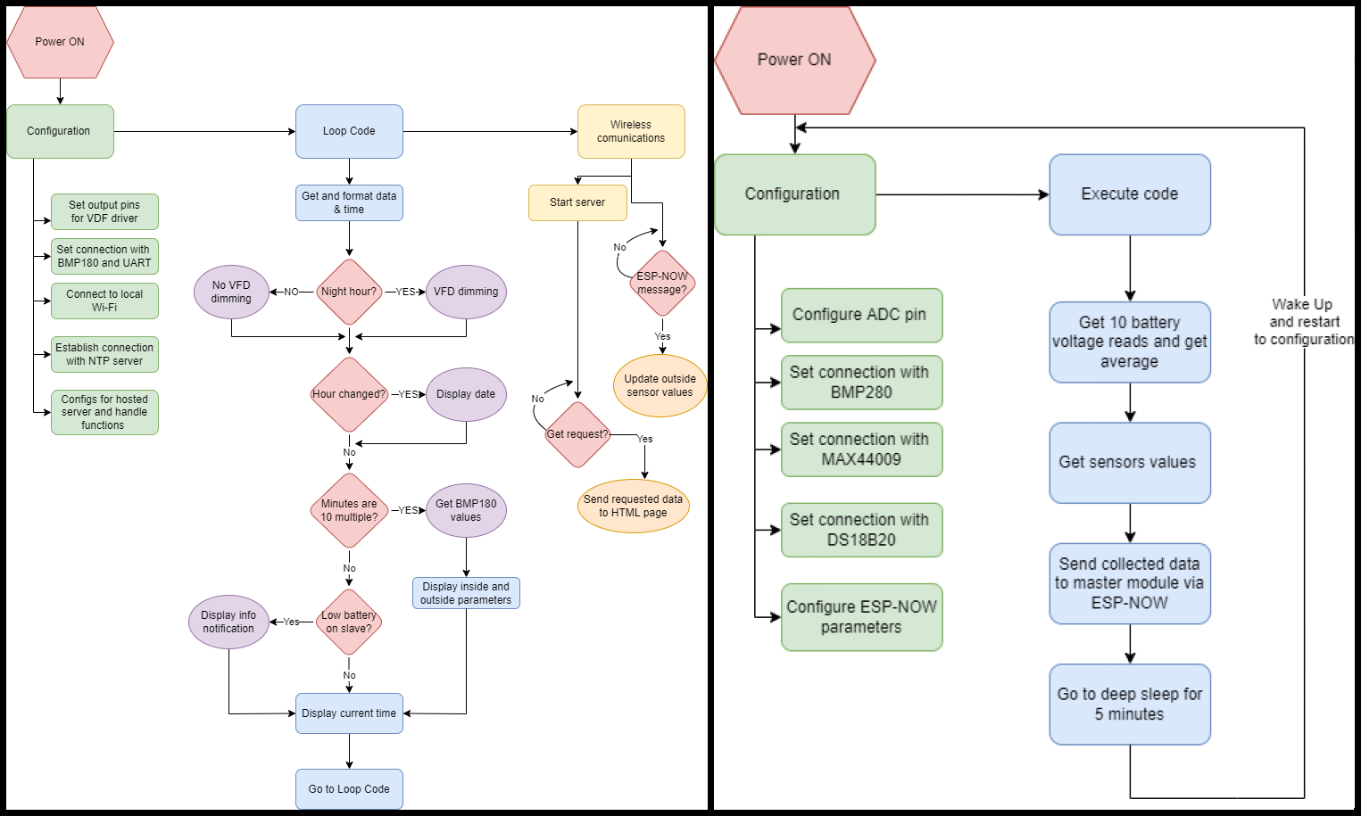
Because cycling from inside parameters to outside parameters, over and over again, I decided to add clock function as idle function. To get current time and date I used ESP32 connected on internet to request NTP packets from a NTP server.
Communication between core and slave station is done using a low power protocol developed by Espressif, ESP-NOW. Connectivity is made via 2.4GHz wireless and is peer to peer, after an initial setup there is not requirements for other handshaking method. ESP-NOW supports the following features
- Encrypted and unencrypted unicast communication.
- Mixed encrypted and unencrypted peer devices.
- Up to 250-byte payload can be carried.
- The sending callback function that can be set to inform the application layer of transmission success or failure.
- Limited encrypted peers to 10 and up to 20 for unencrypted peers
Peers don’t need to be connected on internet; communication is made using MAC address of each peer in the mesh. Payload limit can be a downsize, but the transmission is fast (default at 1 Mbps) so it can be done in multiple steps.
How code works?
- 1. Core station
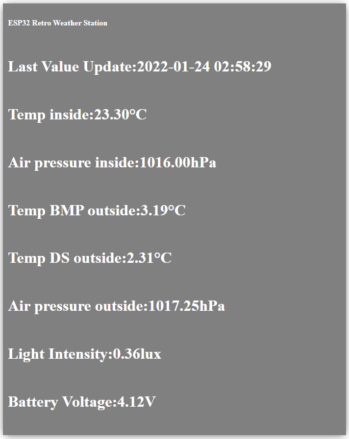
It’s used to grep data from slave station, get and display time and date, display all inside and outside parameters. In this stage at every 10 minutes starting from 0, core station prints in this order:
- Inside temperature
- Inside air pressure
- Outside temperature from BMP280
- Outside temperature from DS18B20
- Outside air pressure
- Outside light illuminance
- Li Ion cell voltage
At every start of a new hour, ESP32 is set to print on display date in YYYY-MM-DD format. Time is displayed in HH-MM-SS 24h format. Another function implemented it dims display brightness based on time interval. Because I use the station daily, during night it lights the room like a green bulb. To avoid that issue, between 20 and 7 brightness is reduce using multiplexing time.
If the battery level is low, a message indicator light will stay on until the battery is replaced or charged. The cell min threshold is 3.6V which is the minimum voltaged that can supply a steady 3.3V at LDO output pin.
To have access to sensors values at any time we can view them on a HTML page hosted by core station. To access the page, when power on the module, it will print IP address for 5 seconds. Values on page are updated using AJAX at every 10 seconds.
- 2. Slave station
To maximize battery life, which is mandatory for an outside unit, ESP32 is in deep sleep for most of time. It’s weak up every 5 minutes and executes: read from sensors, send values and the re-enters sleep. In deep sleep, it’s supposed to consume 10uA, because only RTC timer is on, but due to poor board implementation, LDO and attached sensor, consumption is higher, measured around 0.1mA and when power on current bursts around 200-250mA. To filter high current spikes and effort on LDO, I place an auxiliary cap as a power reservoir.
IV. Schematic, Layout, PCB and Housing
Core Station Schematic
Without a green fillter some unwanted lines are iluminated due to multiplexing.
V. Challenges, conclusion and further development
As a challenges I will say that having 4 voltages rails in a single circuit it's pretty hard to managed. Driving a VFD requires more knowledge and resources than a simple mini OLED or LCD screen. Another challenge is to optimise power consumption in slave station; using a generic ESP32 board is not the best solution to save power and another problem is represented by solar cell, which in my case is to small to overcame the sink current from the modules when ESP32 is in sleep.
In the end, the project is functional, and I used it every day, with no issues, since my last code upload. My vintage clock colection has now a need veritable member.
As future updates I will put on my list the following:
- Get a bigger or more vented case for core station. Sometimes due to the ESP32's heatshield, which is running at full speed to multiplex the VFD and power all Wi-Fi connections, is getting hot and influence BMP180 readings.
- Find a way to use power gating for sensors and ESP32 from slave station to maximise power consumption. I will try to do that using a P-MOS and a low power programmable timer or an PIC/AVR microcontroller which has a small current draw.
- Use a higher quality solar cell to power the Li-Ion charge IC.
- Add more sensors, build more stations and customise user interface from HTML page, maybe adding some custom commands to modify sleep time for slave ESP32, threshold values for battery and display text.

