Smart Hardware Monitor
- Author: Ionel Patrascu
- Email: ionel.patrascu3101@stud.acs.pub.ro
- Master: SRIC
Introduction
Context
The rise of multi-tasking and the increasing demand for seamless user experiences have led to a need for more intuitive and efficient ways to manage information. While traditional methods like pop-up windows or notifications can be disruptive, a dedicated display offering real-time metrics could provide a more discreet and focused approach to managing relevant data.
Problem Description
Current solutions for displaying metrics during active tasks often interrupt the user's workflow. This can be particularly detrimental in activities requiring focus and precision, such as gaming. There is a lack of a dedicated, non-intrusive display solution that can present relevant metrics without requiring users to switch between applications or lose their current focus. This project aims to address this gap by developing an IoT system that utilizes an LCD screen to provide a continuous stream of metrics without disrupting the user's primary activity.
Arhitecture
System Overview
Hardware
ESP32 Development Board with WiFi and Bluetooth 4.2RIP
- Breadboard
- Wires
Circuit Diagram
The circuit diagram showcases a basic setup for the ESP8266 microcontroller, connected to an I2C LCD display and a joystick. The ESP32, a powerful and versatile microcontroller, serves as the central processing unit for the system. It's connected to the LCD display via a set of wires, for 5V, GND, SDA, and SCL. The ESP32 is also connected to the joystick via a set of wires: 3.3V, GND, VRx (analog), SW (digital).
Pinout Scheme
Software
Backend
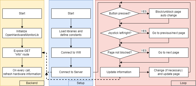
This Python code sets up a Flask web server to provide system hardware information through a REST API endpoint. It first initializes the .NET runtime and imports the OpenHardwareMonitorLib to access hardware data. A Computer object is created, enabling monitoring of CPU, GPU, and RAM. The code then defines a Flask route '/info' that responds to GET requests by collecting data from the enabled hardware sensors, processing it into a dictionary, and returning it as a JSON response. This allows external applications, such as the ESP8266 microcontroller, to retrieve real-time system metrics from the server for display or other purposes.
# Initialize the .NET runtime which we'll use for
# information about the hardware.
clr.AddReference(r'.\OpenHardwareMonitorLib')
from OpenHardwareMonitor.Hardware import Computer

# Create a new Computer instance and enable the CPU, GPU
# and RAM sensors.
c = Computer()
c.CPUEnabled = True # get the Info about CPU
c.GPUEnabled = True # get the Info about GPU
c.RAMEnabled = True # get the Info about RAM
c.Open()

app = Flask(__name__)

@app.route('/info', methods=['GET'])
def get_info():
    # return all the info available
    response = {}
    for hardware in c.Hardware:
        hardware.Update()
        response[hardware.Identifier.ToString()] = {}
        for sensor in hardware.Sensors:
            response[hardware.Identifier.ToString()][sensor.Identifier.ToString()] = sensor.Value

    return jsonify(response)
Api Response Example
The API response is a JSON object containing detailed information about the system's hardware components, including CPU, GPU, and RAM. Each component is represented by a unique identifier, and its individual metrics, such as clock speed, load, power consumption, and temperature, are organized under corresponding sub-identifiers.
{
  "/intelcpu/0": {                           // CPU 0
    "/intelcpu/0/clock/0": 99.9998779296875, // Bus Speed
    "/intelcpu/0/clock/1": 3699.99536132813, // Core 0
    "/intelcpu/0/clock/2": 3699.99536132813, // Core 1
    "/intelcpu/0/clock/3": 3699.99536132813, // Core 2
    "/intelcpu/0/clock/4": 3699.99536132813, // Core 3
    "/intelcpu/0/load/0": 4.15613651275635,  // Load total
    "/intelcpu/0/load/1": 3.78488302230835,  // Load core 0
    "/intelcpu/0/load/2": 4.3637752532959,   // Load core 1
    "/intelcpu/0/load/3": 4.15459871292114,  // Load core 2
    "/intelcpu/0/load/4": 4.32131290435791,  // Load core 3
    "/intelcpu/0/power/0": 2.94126510620117, // Power CPU Package
    "/intelcpu/0/power/1": 1.45460450649261, // Power cores
    "/intelcpu/0/power/2": 0,                // Power graphics
    "/intelcpu/0/power/3": 0.542671918869019,// Power DRAM
    "/intelcpu/0/temperature/0": 51,         // Temperature Core 0
    "/intelcpu/0/temperature/1": 54,         // Temperature Core 1
    "/intelcpu/0/temperature/2": 53,         // Temperature Core 2
    "/intelcpu/0/temperature/3": 52,         // Temperature Core 3
    "/intelcpu/0/temperature/4": 54          // Temperature CPU Package
  },
  "/nvidiagpu/0": {                          // GPU 0
    "/nvidiagpu/0/clock/0": 135,             // GPU Core
    "/nvidiagpu/0/clock/1": 324.000030517578,// Memory
    "/nvidiagpu/0/clock/2": 270,             // Shader
    "/nvidiagpu/0/control/0": 25,            // Fan
    "/nvidiagpu/0/fan/0": 1066,              // Fan Speed
    "/nvidiagpu/0/load/0": 0,                // Load Core
    "/nvidiagpu/0/load/1": 7,                // Load Frame Buffer
    "/nvidiagpu/0/load/2": 0,                // Load Video Engine
    "/nvidiagpu/0/load/3": 0,                // Load Bus Interface
    "/nvidiagpu/0/load/4": 23.1866836547852, // Load Memory
    "/nvidiagpu/0/power/0": 27.2940006256104,// Power GPU
    "/nvidiagpu/0/smalldata/1": 3146.2734375,// VRAM Free
    "/nvidiagpu/0/smalldata/2": 949.7265625, // VRAM Used
    "/nvidiagpu/0/smalldata/3": 4096,        // VRAM Total
    "/nvidiagpu/0/temperature/0": 43,        // Temperature GPU
    "/nvidiagpu/0/throughput/0": 0.00390625, // Throughput PCIE Rx
    "/nvidiagpu/0/throughput/1": 0.0009765625 // Throughput PCIE Tx
  },
  "/ram": {
    "/ram/data/0": 13.5922622680664,         // RAM Used
    "/ram/data/1": 18.3470077514648,         // RAM Free
    "/ram/load/0": 42.556583404541           // RAM Load
  }
}
ESP8266
Constants definition
The constants defined in the code represent various settings and parameters used throughout the program. They are declared using the const keyword, ensuring that their values remain unchanged during program execution.
X_PIN: This constant defines the analog pin (A0) connected to the joystick's X-axis. This pin is used to read the joystick's horizontal position.JOYSTICK_THRESHOLD: This constant defines a threshold value (512) used to determine when the joystick is moved left or right. The analogRead value from the joystick is compared to this threshold to trigger state changes.KEY_PIN: This constant defines the digital pin (D3) connected to the joystick's button. This pin is used to detect button presses.actionDelay: This constant defines the delay (1000 milliseconds) between state changes or actions. It helps to avoid rapid transitions and provides a smoother user experience.ssid: This constant stores the name of the Wi-Fi network the ESP8266 should connect to.password: This constant stores the password for the specified Wi-Fi network.serverAddress: This constant stores the IP address of the server providing the system hardware information.serverPort: This constant stores the port number on the server that the ESP8266 should connect to.stateChangeInterval: This constant defines the interval (10000 milliseconds) at which the display state automatically changes if the joystick is not moved. This ensures that the display cycles through different information even if the user is not actively interacting with the joystick.
These constants provide a clear and organized way to manage the configuration parameters of the ESP8266 system, making the code more readable and maintainable.
Send request function
The sendRequest() function is responsible for retrieving system hardware information from the server. It uses the HTTPClient library to send an HTTP GET request to the specified server address and port, requesting data from the /info endpoint. The function includes error handling to ensure a robust connection.
The function first initializes the HTTPClient object and specifies the server address, port, and endpoint. Then, it enters a loop that continues until a successful response is received from the server. Within the loop, it sends the GET request using http.GET(). If the request fails (returns -1), an error message is printed to the serial monitor, and the LCD displays “Conn Error.” and “Retrying…”. The function then waits for 1 second before retrying the request.
If the request is successful (returns a positive value), the function retrieves the response from the server using http.getString(). This response is then deserialized into a JSON document using the deserializeJson() function, making the hardware data accessible for processing and display. Finally, the function closes the HTTP connection using http.end().
// Function to send the request to the server. It will keep sending the request
// until it gets a response from the server. If the server is down, it will keep
// retrying to connect to the server.
// Output: None but it will update the global JSON document with the latest data
// received from the server (in json format)
void sendRequest() {
  http.begin(wifiClient, serverAddress, serverPort, "/info");
  int httpResponseCode = -1;
  String line = "";
  while (httpResponseCode == -1) {
    // Send the request to the server
    httpResponseCode = http.GET();
    if (httpResponseCode == -1) {
      Serial.println("Error sending request. Is the server up?");
      lcd.clear();
      lcd.setCursor(0, 0);
      lcd.print("Conn Error.");
      lcd.setCursor(0, 1);
      lcd.print("Retrying...");
      delay(1000);
    }
    else
    {
      if (httpResponseCode > 0) {
        line = http.getString();
        // Deserialize the JSON document
        deserializeJson(doc, line);
      }
    }
  }
  http.end();
}
Setup function
The setup() function initializes the ESP8266 microcontroller, setting up the necessary components and establishing communication with the server. It begins by initializing serial communication for debugging purposes and then initializes the LCD display, turning on its backlight. The ESP8266 then attempts to connect to the specified Wi-Fi network using the provided SSID and password. Once connected, it verifies the connection by sending a request to the server and displaying the connection status on the LCD. Finally, the setup() function configures the joystick button pin as an input with a pull-up resistor.
void setup() {
  Serial.begin(115200); // Initialize serial communication for debugging
  // Initialize the LCD
  lcd.init();
  lcd.backlight(); // Turn on backlight (if you have it)
  // Initialize network connection
  connectToWiFi();
  connectToServer();
  // Set the KEY pin as an input with a pull-up resistor for joyztick button
  pinMode(KEY_PIN, INPUT_PULLUP);
  lastStateChangeTime = millis();
}
Loop function
The loop() function is the heart of the ESP8266 program, continuously executing its code to manage the display and respond to user input. It starts by checking for button presses on the joystick. If the button is pressed, the code checks how long it has been pressed. If the button is pressed for more than 2 seconds, the isBlocked flag is toggled, effectively enabling or disabling the automatic state change mechanism. If the button is pressed for less than 2 seconds and the display is not blocked, the current display state is changed to the next state.
Next, the function reads the analog value from the joystick's X-axis. If the value is below a certain threshold, indicating a leftward movement, the current state is changed to the previous state. Conversely, if the value is above another threshold, indicating a rightward movement, the state is changed to the next state.
The function then checks if the display is blocked. If not, it checks if the stateChangeInterval has elapsed since the last state change. If so, the state is automatically changed to the next state.
Finally, the function sends a request to the server to retrieve updated hardware data and then calls the appropriate display function based on the current state. The delay() function is used to introduce a short pause before the loop restarts.
void loop() {
  // Check if the button is pressed
  // If the button is pressed for more than 2 seconds, block the display
  if (digitalRead(KEY_PIN) == LOW) {
    if (buttonPressTime == 0) { // Button just pressed
      buttonPressTime = millis();
    } else if (millis() - buttonPressTime > 2000) {
      // Button pressed for more than 2 seconds
      // Enable/disable display blocking mechanism
      isBlocked = !isBlocked;
      buttonPressTime = 0;
    }
    // If the button is pressed less than 2 seconds, change the display state
    // if the display is not blocked
  } else if (buttonPressTime != 0) {
    if (!isBlocked) {
      currentState = static_cast<DisplayState>((currentState + 1) % NUM_STATES);
    }
    buttonPressTime = 0;
  }
  // Check the joystick value to change the display state
  int joystickValue = analogRead(X_PIN);
  // Check if the joystick is moved left or right
  if (joystickValue < JOYSTICK_THRESHOLD / 2) {
    // Joystick moved left -> Change the display state to the previous state
    currentState = static_cast<DisplayState>((currentState - 1 + NUM_STATES) % NUM_STATES);
    lastStateChangeTime = millis();
  } else if (joystickValue > JOYSTICK_THRESHOLD * 3 / 2) {
    // Joystick moved right -> Change the display state to the next state
    currentState = static_cast<DisplayState>((currentState + 1) % NUM_STATES);
    lastStateChangeTime = millis();
  }
  // Update the display based on the current state if the display is not blocked
  if (!isBlocked) {
    // Change the display state every stateChangeInterval milliseconds
    if (millis() - lastStateChangeTime > stateChangeInterval) {
      currentState = static_cast<DisplayState>((currentState + 1) % NUM_STATES);
      lastStateChangeTime = millis();
    }
  }
  // Call the appropriate function to retrieve updated data and then display it
  // based on the current state and then wait for actionDelay/4 milliseconds
  sendRequest();
  switch (currentState) {
    case OVERALL:
        displayOverall();
        break;
    case CPU:
        displayCPU();
        break;
    case GPU:
        displayGPU();
        break;
    case RAM:
        displayRAM();
        break;
    }

  delay(actionDelay/4);
}
Display Functions
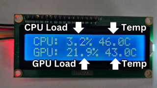
The displayOverall() function is responsible for displaying a concise summary of the system's overall performance on the LCD screen. It retrieves the CPU load, CPU temperature, GPU load, and GPU temperature from the JSON document populated by the sendRequest() function. It then formats this information and displays it on the LCD in two lines.
The function first clears the LCD screen using lcd.clear(). Then, it sets the cursor position to the beginning of the first line (0, 0) using lcd.setCursor() and prints the CPU load and temperature in the format “CPU: XX.X% XX.XC”. It repeats this process for the GPU on the second line (0, 1), displaying the GPU load and temperature in the same format.
void displayOverall() {
  float cpuLoad = doc["/intelcpu/0"]["/intelcpu/0/load/0"];
  float cpuTemp = doc["/intelcpu/0"]["/intelcpu/0/temperature/0"];
  float gpuLoad = calculateGpuLoad(); // There are five GPU sensors, we will the one with the highest load
  float gpuTemp = doc["/nvidiagpu/0"]["/nvidiagpu/0/temperature/0"];
  lcd.clear();
  lcd.setCursor(0, 0);
  lcd.printf("CPU: %.1f%% %.1fC", cpuLoad, cpuTemp);
  lcd.setCursor(0, 1);
  lcd.printf("GPU: %.1f%% %.1fC", gpuLoad, gpuTemp);
}
Similar functions, displayCPU(), displayGPU(), and displayRAM(), are implemented to provide more detailed information about each hardware component, respectively. These functions follow a similar structure, retrieving relevant data from the JSON document and displaying it on the LCD in a user-friendly format.
Results
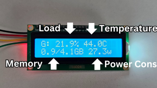
 This section presents the visual results of the implemented system, showcasing the information displayed on the LCD screen for each of the four display states.
Overall Page
The “Overall” page provides a concise overview of the system's performance, displaying the CPU load and temperature alongside the GPU load and temperature. This page offers a quick glance at the system's general health and resource utilization.
CPU Page
The “CPU” page provides more detailed information about the CPU, displaying the CPU load, temperature, frequency, and power consumption. This page allows for a more in-depth analysis of the CPU's performance and resource usage.
GPU Page
The “GPU” page focuses on the GPU's performance, displaying the GPU load, temperature, memory usage, and power consumption. This page provides insights into the GPU's workload and resource utilization.
RAM Page
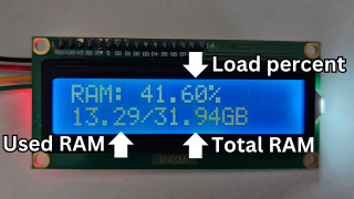 The “RAM” page displays the RAM usage, showing the amount of RAM currently used and available. This page helps monitor the system's memory utilization and identify potential memory constraints.
Real-World Setup
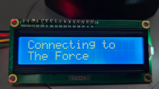
 This image showcases the actual physical setup of the project. The ESP8266 microcontroller is connected to the LCD display and the joystick, allowing for user interaction and real-time display updates. The ESP8266 communicates with the server to retrieve system hardware data, providing a seamless and informative experience for the user. This image highlights the practical implementation of the project, demonstrating its functionality and user-friendliness.
Conclusion and Future Work
The project successfully demonstrates the implementation of a real-time system hardware monitoring solution using an ESP8266 microcontroller, an LCD display, and a joystick for user interaction. The system effectively retrieves system hardware data from a server via a Flask API and displays it on the LCD in a user-friendly format. The user can navigate between different display states showcasing various system metrics using the joystick and its button. The system provides a valuable tool for monitoring system performance without interrupting the user's primary activity.
Future work could focus on enhancing the user experience and functionality of the system. One potential improvement would be to replace the current LCD display with a larger, more visually appealing display. A graphical user interface (GUI) could be developed to present the information in a more intuitive and engaging way. Additionally, exploring the integration of additional sensors, such as temperature sensors or fan speed sensors, could provide a more comprehensive view of the system's health and performance.
References
- OpenHardwareMonitor Library: https://github.com/OpenHardwareMonitor/OpenHardwareMonitor
- Flask Web Framework: https://flask.palletsprojects.com/
- ESP8266 WiFi Library: https://github.com/esp8266/Arduino
- ESP8266 HTTPClient Library: https://github.com/esp8266/Arduino/tree/master/libraries/ESP8266HTTPClient
- ArduinoJson Library: https://arduinojson.org/
- LiquidCrystal_I2C Library: https://github.com/johnrickman/LiquidCrystal_I2C
- How to Use I2C LCD with ESP32 on Arduino IDE (ESP8266 compatible): https://randomnerdtutorials.com/esp32-esp8266-i2c-lcd-arduino-ide/
- ESP8266 Pinout Reference: https://randomnerdtutorials.com/esp8266-pinout-reference-gpios/


