WiFi-controlled surveillance system
Student: Costin-Emanuel Vasile (ACES)
All the materials, including the source code and presentation, are here
1. Project overview
The project is a smart embedded system that utilizes an ESP32-CAM board mounted on a plexiglass car chassis.
The ESP board serves as the brain of the system, hosting a web platform that allows users to access the live video feed from the camera and remotely control the movement of the car. The system is equipped with a variety of commands, including change of movement state and the state of the light.
This provides a convenient and user-friendly way to control the movement of the car remotely and explore its surroundings.
2. Hardware
ESP32-CAM
 The ESP32-CAM is a development board that combines the functionality of the ESP32 microcontroller and a camera. Some of the key features of the ESP32-CAM include:
- Dual-core microcontroller: The ESP32-CAM is based on the ESP32 microcontroller, which has two 32-bit cores running at up to 240 MHz
- Built-in camera: The ESP32-CAM has a built-in camera module with a resolution of up to 1080p. This allows the system to capture and stream video in real-time
- Wi-Fi and Bluetooth: The ESP32-CAM has built-in support for Wi-Fi and Bluetooth, which can be used to connect to a network and communicate with other devices
FT232RL USB-Serial converter
The FT232RL chip is a very useful component because it allows you to easily connect the ESP32-CAM to a computer and communicate with it, which is essential for programming, testing, and debugging the system.
The chip converts the USB signals from the computer into UART serial interface signals that the ESP32-CAM can understand and vice-versa. This allows to upload code to the ESP32-CAM and also send commands or receive data from it through the serial interface.
In addition to programming and debugging, the module equiped with FT232RL is also used to power the ESP32-CAM module during normal execution, as it has a USB input and 5V/GND wire outputs.
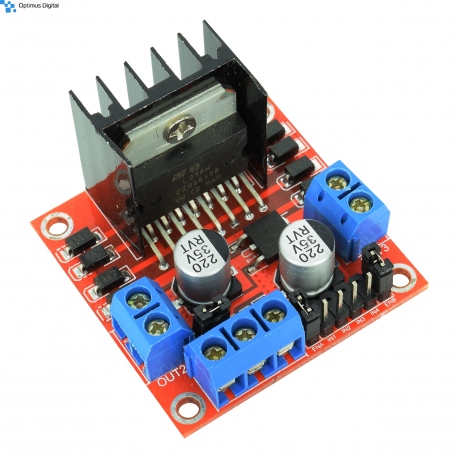
L298N module
 The L298N module is a type of motor driver that is used to control DC motors. It is based on the L298 H-bridge IC, which is a popular integrated circuit for controlling the speed and direction of DC motors. The L298N module is a breakout board that includes the L298 IC, as well as some additional components such as diodes and transistors, to provide a convenient and easy-to-use motor control solution.
The L298N module works by using H-bridge circuit to control the voltage applied to the DC motors. An H-bridge is a type of circuit that allows the direction of current to be reversed, which in turn allows the direction of the motor's rotation to be controlled. The L298N module has four inputs that can be used to control the motor: two inputs for controlling the direction of rotation (IN1 and IN2), and two inputs for controlling the speed of the motor (EN1 and EN2).
Plexiglass chassis kit with DC motors
 The plexiglass car chassis is used to hold all the components in place and provide a structure for the car. It is equiped with two DC motors rated for a voltage operation of 5V-12V.
Schematic diagram
 The source of the schematic can be found here.
3. Software
The starting point of this project was the official ESP32-CAM webserver example which can be found in this repository, which I simplified and changed to fit the needs of the project.
The main functions that the module has to do are the following:
- Connect to WiFi to be accessible from local network
- Host a web platform to provide access to the video stream and movement controls
- Drive the motors according to the commands received from the user through the web platform
The updates I added to the initial code are detailed below.
Simple HTML index
From the initial HTML index I removed all the controls available and kept only the video stream and flashlight controlls. On top of this I added the code for the five buttons:
- Added the buttons in the body of the HTML:
        <button id="drive_stop" style="float:left;" title="">Stop</button>
        <button id="drive_front" style="float:left;" title="">Front</button>
        <button id="drive_back" style="float:left;" title="">Back</button>
        <button id="drive_left" style="float:left;" title="">Left</button>
        <button id="drive_right" style="float:left;" title="">Right</button>
- Added the behavior of the buttons in the <script> side of the HTML index:
    const driveStopButton = document.getElementById('drive_stop')
    const driveFrontButton = document.getElementById('drive_front')
    const driveBackButton = document.getElementById('drive_back')
    const driveLeftButton = document.getElementById('drive_left')
    const driveRightButton = document.getElementById('drive_right')

        driveStopButton.onclick = () => {
      var xhr = new XMLHttpRequest();
      xhr.open('post', 'http://192.168.0.128/?direction=stop', true);
      xhr.setRequestHeader('Content-Type', 'application/x-www-form-urlencoded; charset=UTF-8');
      xhr.send();
    }
    driveFrontButton.onclick = () => {
      var xhr = new XMLHttpRequest();
      xhr.open('post', 'http://192.168.0.128/?direction=front', true);
      xhr.setRequestHeader('Content-Type', 'application/x-www-form-urlencoded; charset=UTF-8');
      xhr.send();
    }
    driveBackButton.onclick = () => {
      var xhr = new XMLHttpRequest();
      xhr.open('post', 'http://192.168.0.128/?direction=back', true);
      xhr.setRequestHeader('Content-Type', 'application/x-www-form-urlencoded; charset=UTF-8');
      xhr.send();
    }
    driveLeftButton.onclick = () => {
      var xhr = new XMLHttpRequest();
      xhr.open('post', 'http://192.168.0.128/?direction=left', true);
      xhr.setRequestHeader('Content-Type', 'application/x-www-form-urlencoded; charset=UTF-8');
      xhr.send();
    }
    driveRightButton.onclick = () => {
      var xhr = new XMLHttpRequest();
      xhr.open('post', 'http://192.168.0.128/?direction=right', true);
      xhr.setRequestHeader('Content-Type', 'application/x-www-form-urlencoded; charset=UTF-8');
      xhr.send();
    }
Camera server
For the server configuration I declared and registered a new URI handler as follows:
    httpd_uri_t direction_index_uri = {
        .uri       = "/",
        .method    = HTTP_POST,
        .handler   = direction_index_handler,
        .user_ctx  = NULL
    };

    httpd_register_uri_handler(camera_httpd, &direction_index_uri);
The handler registers the following function used to answer to the requests:
static esp_err_t direction_index_handler(httpd_req_t *req){
    char*  buf;
    size_t buf_len;
    char dir[32] = {0,};

    buf_len = httpd_req_get_url_query_len(req) + 1;
    if (buf_len > 1) {
        buf = (char*)malloc(buf_len);
        if(!buf){
            httpd_resp_send_500(req);
            return ESP_FAIL;
        }
        if (httpd_req_get_url_query_str(req, buf, buf_len) == ESP_OK) {
            if (httpd_query_key_value(buf, "direction", dir, sizeof(dir)) == ESP_OK) {
            } else {
                free(buf);
                httpd_resp_send_404(req);
                return ESP_FAIL;
            }
        } else {
            free(buf);
            httpd_resp_send_404(req);
            return ESP_FAIL;
        }
        free(buf);
    }

    Serial.print("New movement request: "); Serial.println(dir);
    drive(dir);
    return ESP_OK;
}
The function above calls the method below which I implemented to drive the motors using the H-bridge module. It sends a PWM signal to the module by calling the built-in Arduino method called ledcWrite.
The pin used to control each side of the H-bridge was mapped to a different PWM output of the ESP32-CAM board. This PWM output represents the first argument of the ledcWrite function, the second being the duty-cycle (where 0 means 0% and 255 means 100% duty-cycle).
void drive(char* dir){
        ledcWrite(0, 0);
        ledcWrite(1, 0);
        ledcWrite(2, 0);
        ledcWrite(3, 0);

    if(strcmp(dir, "right") == 0){
        ledcWrite(0, 150);
        ledcWrite(1, 0);
        ledcWrite(2, 150);
        ledcWrite(3, 0);
    }
    else if(strcmp(dir, "left") == 0){
        ledcWrite(0, 0);
        ledcWrite(1, 150);
        ledcWrite(2, 0);
        ledcWrite(3, 150);
    }
    else if(strcmp(dir, "back") == 0) {
        ledcWrite(0, 0);
        ledcWrite(1, 170);
        ledcWrite(2, 170);
        ledcWrite(3, 0);
    }
    else if(strcmp(dir, "front") == 0) {
        ledcWrite(0, 170);
        ledcWrite(1, 0);
        ledcWrite(2, 0);
        ledcWrite(3, 170);
    }
}
4. Results and demonstration
I uploaded a demonstrative video here.
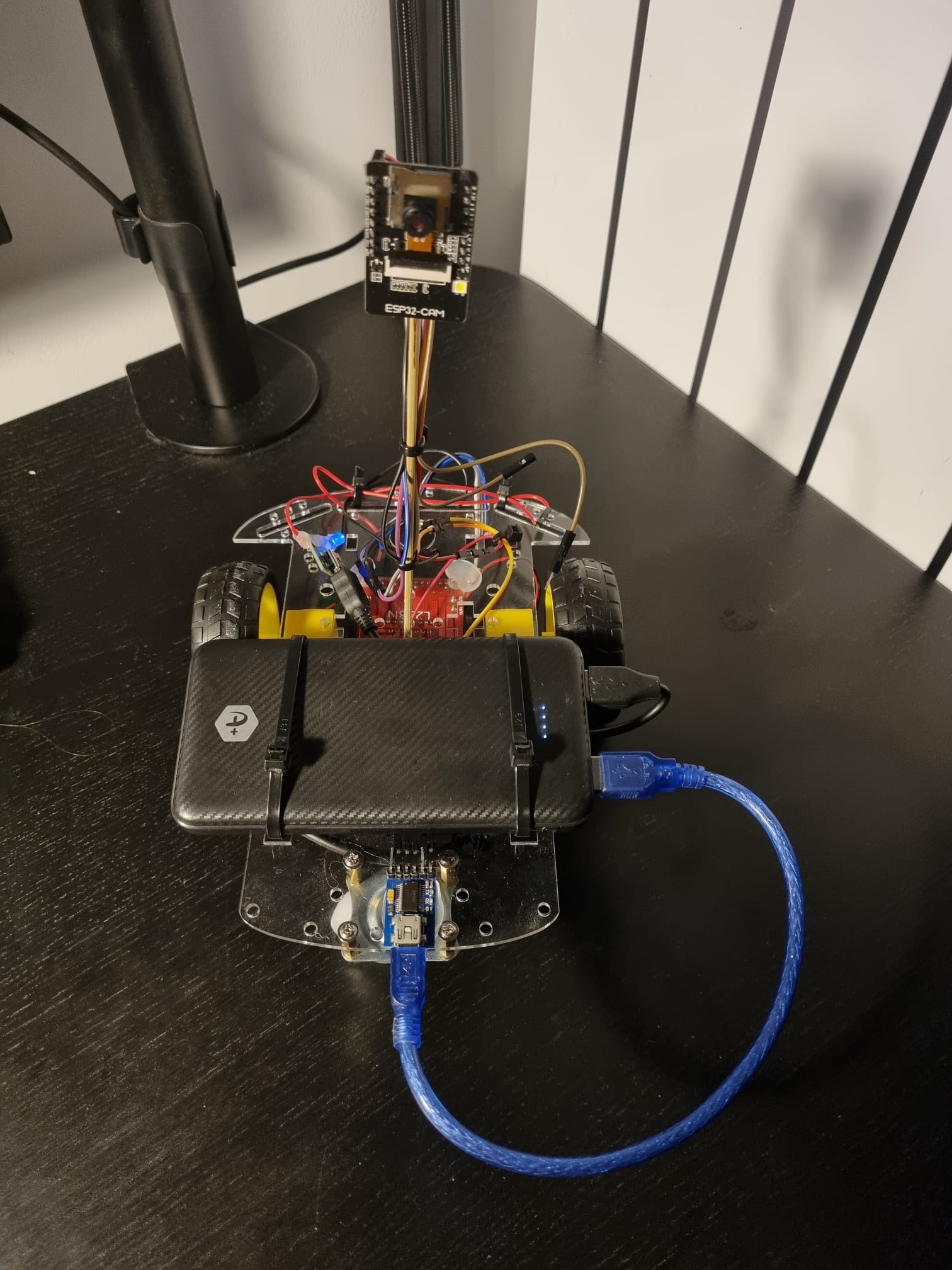
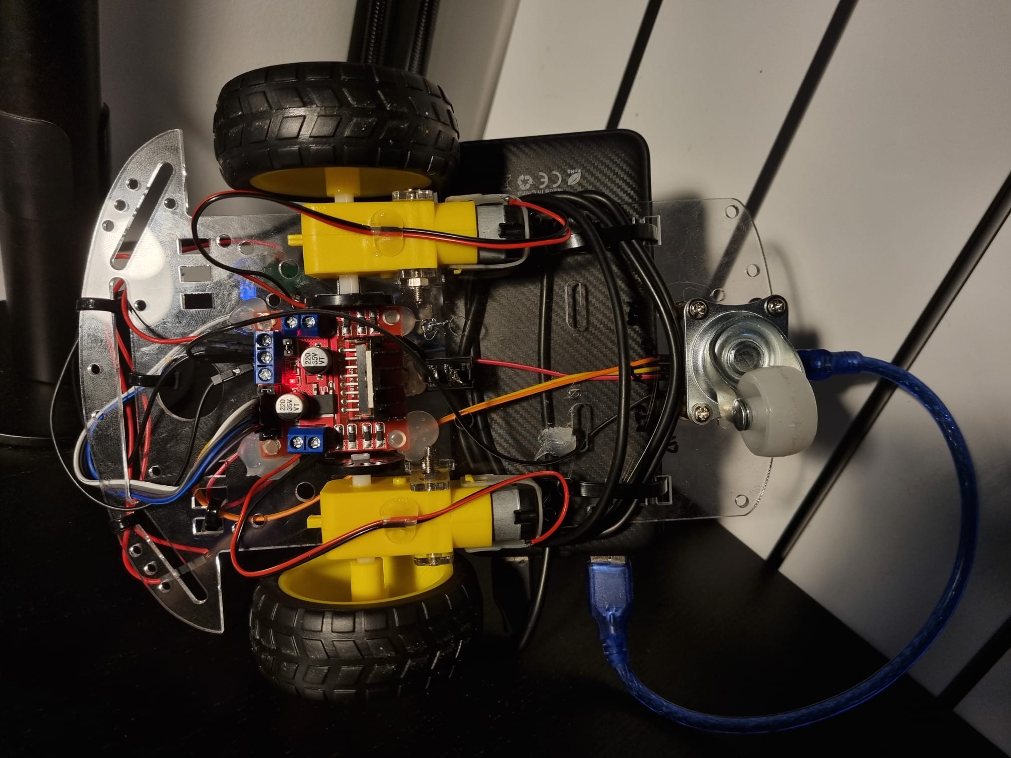
Below are some images with the final prototype of the car.


