Long distance wireless communication
Introduction
This project has as final purpose, transmitting sensor data over a long distance, to a node which is an internet gate (in this case the ESP32 node) and from there to plot received data on a chart from a website created by the ESP32.
Hardware
Bill of materials (BOM)
- 1 x ESP32 WROVER KIT (in this case: T18 3.0)
- 2 x Arduino board (any, just to have SPI. In this case is Uno)
- 2 x nRF24L01 modules
- 1 x Sound sensor
- 1 x 9V battery
- wires
Schematic
Experimental setup
Description of the setup
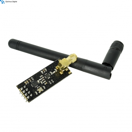
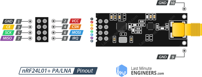
1. nRF24L01+ PA + LNA
It is a low cost wireless communication module, created by Nordic Semiconductor, that comes with an antenna for long distance range. There are libraries written to provide API and easy compatibility with Arduino. It's range varies from 250m to 1100m. Maybe the most helpful feature is has is that the communication range can be traded-off with the data bandwidth. Possible combinations are:
2Mbps for 250 meters,
1Mbps for 500 meters,
250kbps for 1100 meters (open field)
It's frequency in the 2.4 GHz ISM band, or more precisely, any frequency between 2.400 and 2.525 GHz (2400 to 2525 MHz). Also one channel has a bandwidth of almost 1MHz, means that it gives us 125 possible channels with a 1MHz spacing.
PA stands for Power Amplifier and LNA stands for Low-Noise Amplifier its function is to amplify an extremely weak signal received from the antenna.
Also it is worth mentioning that one device can communicate up to 8 devices.
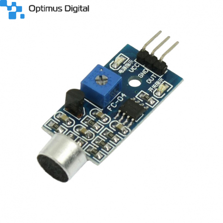
2. Sound sensor module
This is very cheap sound sensor, with a very simple interface, with digital output.
This module contains a trigger Schmitt, so it can only detect sound presence and can not be used to measure sound intensity, frequency or any analog parameter.
It also contains an potentiometer to adjust the offset of the amplifier for the specific application.
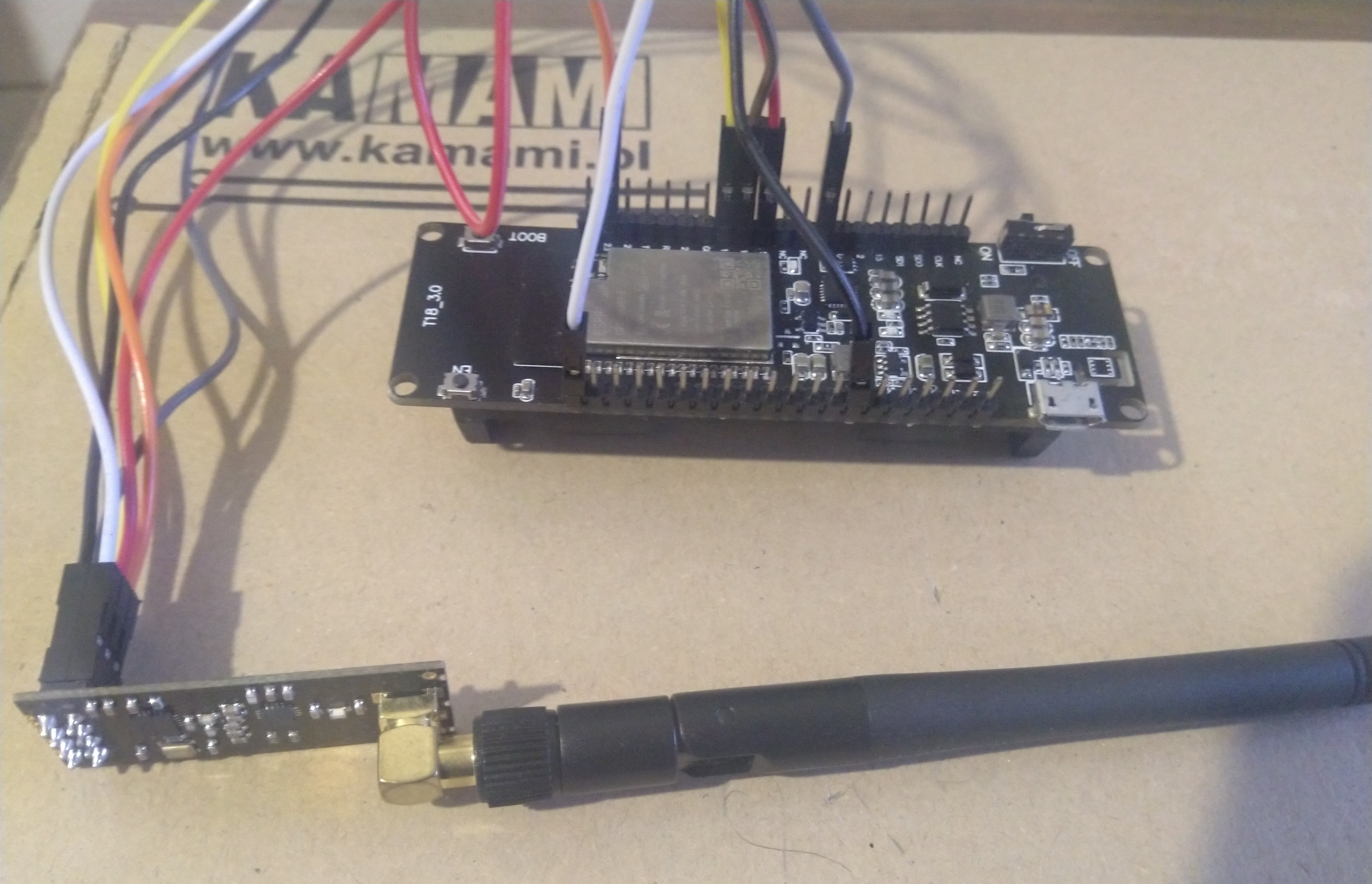
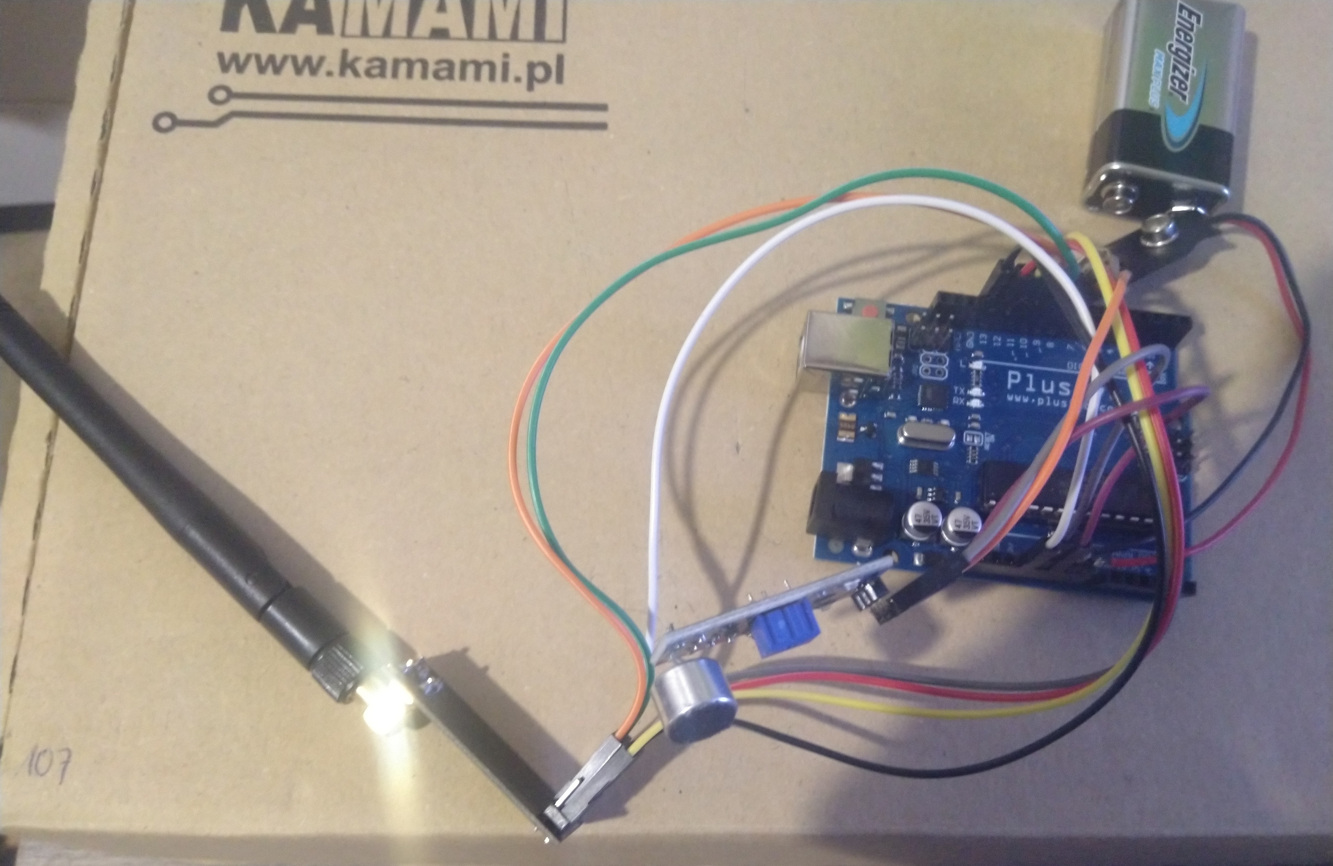
Real setup
As can the seen, the Arduino board has to be powered from battery because it will be placed far away from the computer.
Software
Tools used: Arduino IDE, nRF24L01 library.
Because the nRF24L01 module is using SPI communication, step zero is to assure the ESP32 TTY board supports SPI communication and find out pins of this specific module board. Easy task, just run a small script to findout SPI pinouts: 'MISO', 'MOSI', 'SS', 'CLK'.
Next step is to establish the wireless communication between the 2 master modules: Arduino and ESP32.
Arduino is the transmitter and ESP32 is the receiver.
A demo code for the Arduino (Uno - matters only for the pinout) can be seen in the code appendix 1).
And the ESP32 will be the received, code example here 2).
(note: nRF24L01 module can operate in full duplex mode, but in this project, only one way communication was used).
It is very important to test the setup in the environment in which will be used, because the distance between the 2 nodes can vary from 1100m in open field to even meter in, for example, concrete walls on the way.
After the communication between the modules was established, it is time to send real data from the sound sensor.
As stated in the description of the sound sensor module, it can only transmit digital level to detect sound, not reply sound fidelity.
So in order to hack this ![]() a simple script to count time while sound level is high was used.
a simple script to count time while sound level is high was used.
Visualizing such data in the Serial Plotter, looks like a real microphone recording. Code is the appendix 3)
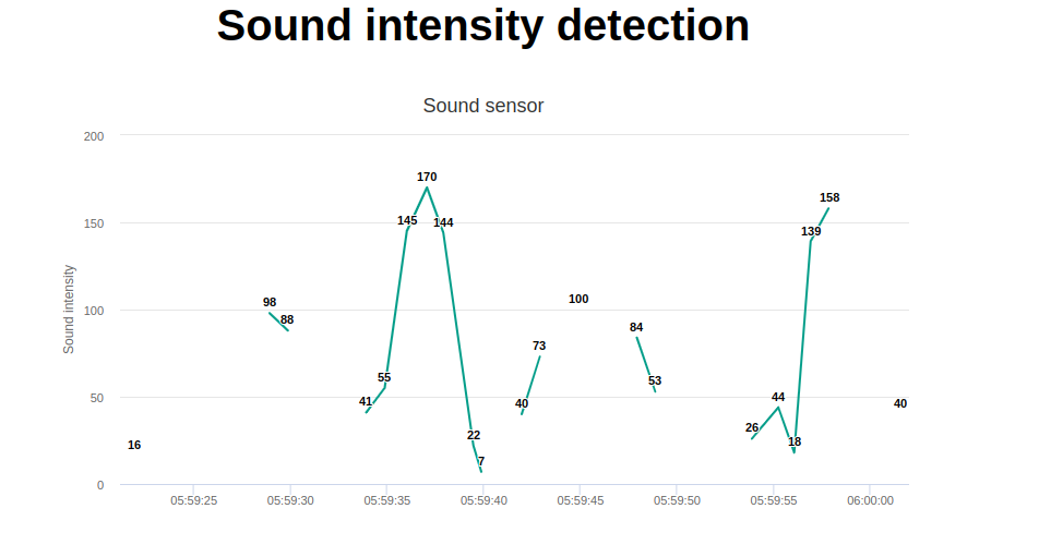
Last step is to create a web page hosted by the ESP32, that will be accessed by a PC to view collected data on charts.
For this, laboratory 3 was used:
https://ocw.cs.pub.ro/courses/iothings/laboratoare/2022/lab3
Final information plotted in a chart on the webpage look like:
Bibliography
http://www.iotsharing.com/2018/03/esp-and-raspberry-connect-with-nrf24l01.html/
https://lastminuteengineers.com/nrf24l01-arduino-wireless-communication/
Appendix
Arduino transmitter code example:
#include <SPI.h>
#include "nRF24L01.h"
#include "RF24.h"
char msg[10] = "Hello!";

#define CE_PIN 9
#define CSN_PIN 10

RF24 radio(CE_PIN, CSN_PIN);

const uint64_t pipe = 0xE8E8F0F0E1LL;

void setup(void){
  radio.begin();
  radio.setChannel(2);
  radio.setPayloadSize(7);
  radio.setDataRate(RF24_250KBPS);
  radio.openWritingPipe(pipe);
}

void loop(void)
{
    radio.write(msg, 10);
    delay(100);
}
ESP32 received code example:
#include <SPI.h>
#include "nRF24L01.h"
#include "RF24.h"
char msg[10];
#define CE_PIN 4
#define CSN_PIN 5
RF24 radio(CE_PIN, CSN_PIN);
const uint64_t pipe = 0xE8E8F0F0E1LL;

void setup(void){
 Serial.begin(115200);
 radio.begin();
 radio.setChannel(2);
 radio.setPayloadSize(7);
 radio.setDataRate(RF24_250KBPS);
 radio.openReadingPipe(1,pipe);
 radio.startListening();
}

void loop(void){
 if (radio.available()){
     radio.read(msg, 6);
     Serial.println(msg);
     delay(100);
 }
 else{
 }
}
Sound sensor code:
int soundPin = A0;

const int OUT_PIN = 8;
const int SAMPLE_TIME = 10;
unsigned long MillisCurrent;
unsigned long MillisLast;
unsigned long MillisElapsed;
int SampleBufferValue = 0;

void setup(void){
 Serial.begin(115200);
}

void loop(void)
{
    MillisCurrent = millis();
    MillisElapsed = MillisCurrent - MillisLast;
    if(digitalRead(OUT_PIN) == HIGH)
    {
      SampleBufferValue++;
    }

    if(MillisElapsed > SAMPLE_TIME){
      Serial.println(SampleBufferValue);
      SampleBufferValue = 0;
      MillisLast = MillisCurrent;
    }
}


