Wi-fi thermostat
Alin Stroe - ACES 2021
Introduction
The application monitors the room temperature and is trying to decrease it or increase it in order to achieve the desired temperature. I will use a temperature sensor (Bosch BME280) which will communicate the temperature and humidity to the micro-controller. The temperature level and the reference one will be displayed on a LCD but also on a web page. When the temperature increases too much (above the desired temperature) the cooling system will turn on (I will use a relay to accommodate all AC appliances but for the demo I will use a DC fan). If this action will decrease the temperature value enough, the cooling system will be turned off. The same algorithm will be used for the other case when the heating system needs to be turned on. The reference temperature(desired temperature) can be set using the web interface or by pressing the hardware buttons of the device (UP/DOWN).
Also the hysteresis interval can be set from a predefined list (e.g. ±0.25ºC, ±0.50ºC).
Hardware components
- ESP32 with Wi-fi connectivity
- LCD 1602 parallel
- Bosch BME280 weather sensor
- 2x Buttons
- 2x Relays
- 2x 10K resistor
- 2x 100nF ceramic capacitor
- 1x 220ohm resistor
- Power supply circuit (in order to obtain different voltage levels for components)
Schematic
Software
The software component is developed using Arduino IDE with the board manager support for ESP32 (LOLIN32 v1.0.0)
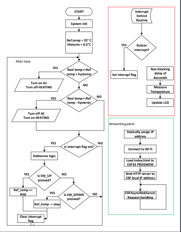
The software diagram is found below.
Figure 2. Software diagram
I will describe the code on sections (data acquisitions, data outputs and control, Asynchronous web server for ESP32).
Data acquisitions
Bosch BME280
Data is collected from the Bosch BME280 sensor using Adafruit library:
#include <Adafruit_Sensor.h>
#include <Adafruit_BMP280.h>
But also the event support in order to trigger the sensor measurement.
The sensor is using the I2C interface (SDA and SCL pins connected to the I2C bus → pin 21 and 22 of the ESP32 board)
 String readBMETemperature() {
  bmp_temp->getEvent(&temp_event);
  real_temp = temp_event.temperature;
  return String(real_temp);

 }
Buttons
I used two push buttons for the setting of the desired temperature (UP/DOWN). The setting step is 0.5ºC.
In order to integrate the buttons functionality without blocking the entire execution of the main program (mainly webserver and LCD refreshment would be affected) I used interrupt functionality of ESP32 by defining and Interrupt Service Routine (ISR) that would be executing when an external events would occur. In this case the external event is by pulling a specific GPIO pin to logic HIGH by using an external push button. When the signal connected to that GPIO is driven with a transition LOW-HIGH, the ISR function will be executed.
  pinMode(BUTTON_MINUS, INPUT);
  pinMode(BUTTON_PLUS, INPUT);
  attachInterrupt(BUTTON_MINUS, ISR_func, RISING);
  attachInterrupt(BUTTON_PLUS, ISR_func, RISING);

  void IRAM_ATTR ISR_func()
  {
    interrupt_flag = true;
  }
Because the push buttons is mechanically making contact between its pins, this contact is not perfect so the bouncing effect appears, which makes the micro controller count the bouncing between HIGH-LOW states as a valid transition. To overcome this effect I used two techniques: hardware and software de-bounce.
For hardware de-bounce I used a 100nF ceramic capacitor connected between a button pin and GND. This capacitor affects the rise time of the signal that is connected to ESP32 pin and thus limits the bouncing effect by slowing the transitions. Another addition to set the idle state of the ESP32 GPIO is a 10k resistor tied to GND.
The software technique of getting rid of the bounce effect is by using millis() function to implement a non-blocking delay with the purpose of waiting around 50 milliseconds (empirically determined) after the first transition registered on the interrupt pin, after this period the signal settles to trigger state (GND).
    if (interrupt_flag == true)
   {
      if ((currentTime - lastIntTime)> 50 && interrupt_flag)
        {  lastIntTime = currentTime;
           if(digitalRead(BUTTON_PLUS))
              {
                 ref_temp+=REF_TEMP_STEP;
              }
           else if(digitalRead(BUTTON_MINUS))
              {
                ref_temp-=REF_TEMP_STEP;
              }
      update_LCD();
      interrupt_flag = false;

        }
  }
Data output and control
LCD
The data output is implemented using the parallel LCD1602.
I used the LiquidCrystal library I wrote a function update_LCD() which is called every 4 seconds to refresh the LCD Display.
In this function I have also implemented a method that displays the desired temperature setup each time a button(PLUS/MINUS) is pressed.
void update_LCD(){
   lcd.clear();
   if(!interrupt_flag){
       readBMETemperature();
       readBMEPressure();
       lcd.setCursor(0,0);
       lcd.print("Temp = ");
       lcd.print(real_temp);
       lcd.print(" *C");
       lcd.setCursor(0,1);
       lcd.print("Pres = ");
       lcd.print(pressure_event.pressure);
       lcd.print("hPa");
     }
  else {
      lcd.setCursor(0,0);
      lcd.print("Set temp = ");
      lcd.print(ref_temp);
      lcd.print(" *C");
  }
}
Relays
The control part is represented by the 2 AC relays(230V - 10A) used to turn on/off the heating and cooling system of the house.
The control algorithm uses the desired temperature and the real temperature of the room and compares them.
The hysteresis value can be set from the web interface (±0.25 ºC, ±0.50 ºC) and it represents the difference between the real temperature and the desired temperature that would trigger one of those 2 relays (Heating or Air-Conditioning system).
The relays are coupled when the INPUT signal of the relay is driven to GND. So the initial value for the relay to be in OFF state is logic HIGH. The ON state is LOW.
  if(real_temp>= ref_temp + HYSTERESIS)
          { //Turn on air-conditioning system
            digitalWrite(RELAY_AC,LOW);
            digitalWrite(RELAY_HEATING,HIGH);
          }
          else if (real_temp <= ref_temp - HYSTERESIS)
          { //Turn on heating system
            digitalWrite(RELAY_HEATING,LOW);
            digitalWrite(RELAY_AC,HIGH);
          }
          else {//Turn off both relays
                digitalWrite(RELAY_HEATING,HIGH);
                digitalWrite(RELAY_AC,HIGH);
          }
Asynchronous Web server
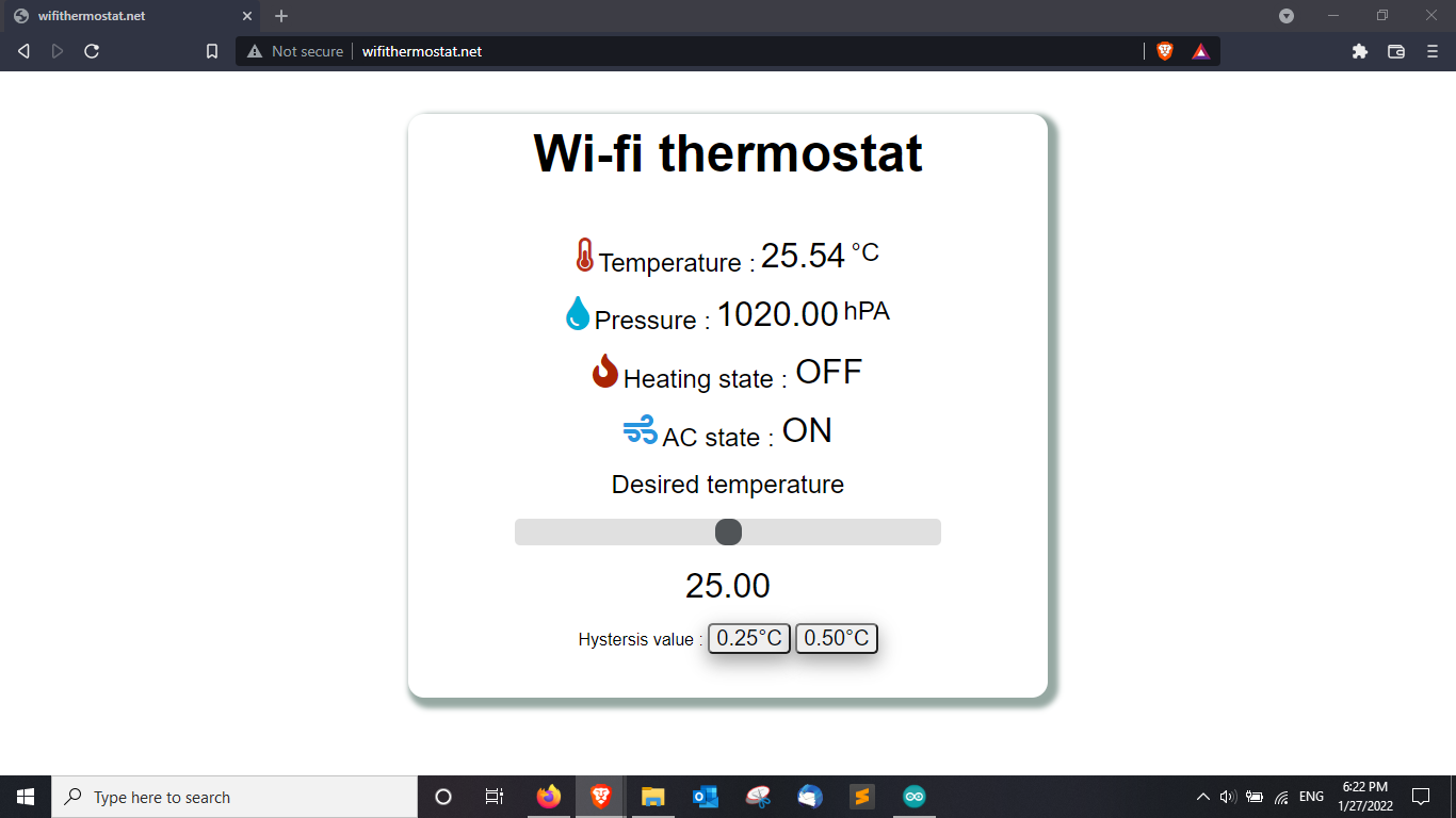
The thermostat can be managed via an web interface from which you can monitor the room temperature and humidity, the state of the heating and AC systems but also from which you can set the desired temperature and the hysteresis interval.
Wi-fi component
Network connectivity is a must for this project because of the need to control our room temperature remotely. The main reason for choosing ESP32 board for this project is the on-board Wi-fi card and the library support which easy to use API functions.
Javascript support
The page needs to update the values without refreshing and also to be able to handle many clients at the same time so the page so the page needs an asynchronous component. In order to achieve this functionality I used the following library:
#include "ESPAsyncWebServer.h"
Which has support for Javascript and offers a easy way to handle requests from multiple clients but also offers the possibility to achieve superior functionality than the basic HTML page (e.g callback functions, triggers).
An example of using the ESPAsyncWebServer.h is the following:
//Defining the way the server handle a temperature request
server.on("/temperature", HTTP_GET, [](AsyncWebServerRequest *request){
   request->send_P(200, "text/plain",readBMETemperature().c_str() , processor);
 });
in which processor is a function that replaces all the placeholders in the HTML page with the value provided by the ESP32 board (e.g. temperature value)
On HTML side, the temperature I used a Javascript function updateTemperature to create a GET request for the temperature each seconds by using the built-in setInterval.
 setInterval(function ( ) {
   updateTemperature();
 }, 1000 )
 function updateTemperature(){
    var xhttp = new XMLHttpRequest();
    xhttp.onreadystatechange = function() {
    if (this.readyState == 4 && this.status == 200) {
        document.getElementById("temperature").innerHTML = this.responseText;
        }
    };
    xhttp.open("GET", "/temperature", true);
    xhttp.send();
  }
Index HTML page (with CSS integration)
I used CSS for achieving a better GUI.
To display the values retrieved from the ESP32 board (sensor values, relay state) I used a placeholder in the HTML code which will be replaced with the sensor value by the processor function.
Placeholders are delimited with % symbols. Like this: %TEMPLATE_PLACEHOLDER%.
For setting the desired temperature I used a range slider with values from 0 to 40ºC with a step of 0.5ºC.
For setting the hysteresis interval I have implemented two buttons for 0.25 and 0.50 values.
Figure 3. Web configuration page
Conclusions
I managed to obtain a basic thermostat functionality with Wi-fi connectivity and capable web-management of controlling two AC appliances (for heating and cooling). By implementing this project, I learned to use various libraries to host a web server on an embedded device with limited resources while also achieving an offline version of the thermostat.
When the Wi-fi network is not reachable, the thermostat is still usable and can be controlled via two external hardware buttons (e.g. for setting up the desired temperature) while the room temperature monitoring is done by the LCD 1602 display.
The web page can be further developed to achieve other functionalities like allowing the user to pre-program the thermostat to maintain a different temperature depending on the current time and day (e.g. Sunday at 8 AM the desired temperature is 24ºC but at 12PM the desired temperature will be 23 ºC)


