Smart Home Bluetooth System
Student: Ionescu Sergiu, ACES
Code archive:
Presentation:
1. Introduction. Description of the project
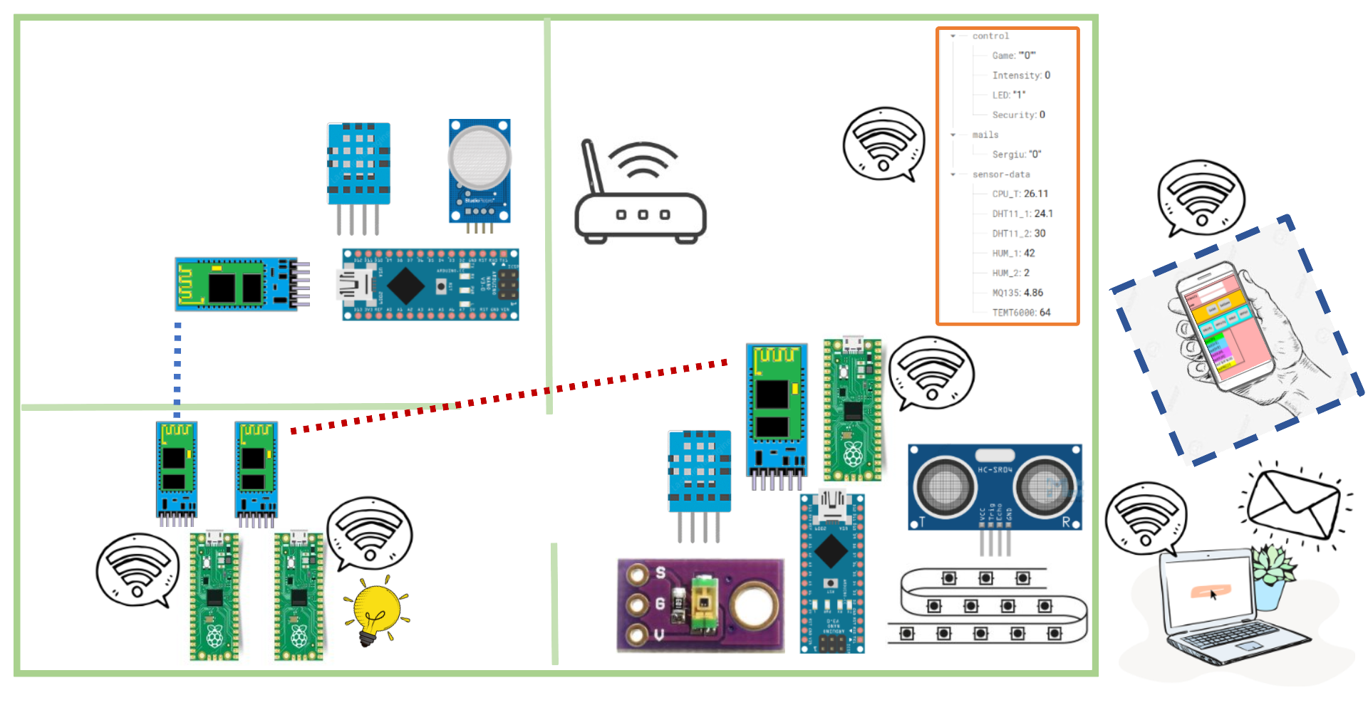
The purpose of this project was to make a basic smart home system using wireless communication between the nodes. The architecture is based on the IoT level 5. Furthermore, the project constitutes the basics for a bigger future project. I will basically have one node monitoring the living room and one node monitoring the kitchen ( so far ). They will communicate with a gateway node using bluetooth, which is a raspberry pi pico w system at its base. However, the raspberry pi pico was not powerful enough to maintain the control for the entire system…so I needed the help of other 2 picos. In the future I plan to replace the picos with an Intel Nuc or a Raspberry Pi. The data that was collected was stored in a Google Firebase and could be monitorized accesing the database using any PC or using an Android app that I made using MIT APP inventor.
The 2 nodes that are monitoring the rooms have the following utilities :
- the kitchen node monitors the temperature, humidity and the level of gas in the room
- the living room node monitors the temperature, humidity, light intensity and also can control a LED strip in various ways, including lighting up the strip according to the distance you are at. Also there is another functionality that notifies me whether I got new mail, and it does it by controlling an LED.
2. Hardware components and wiring
The hardware components needed for this project are:
- 3 x Raspberry Pi PicoW
- 2 x Arduino Nanos
- 4 x HC-05 Bluetooth Modules
- 3 x Breadboard
- Jumper wires
- 220 Ohm and 10 kOhm resistors
- LED Strip
- Micro and Mini USB data cable
- Android Smartphone to run the monitoring application
- Sensors
- HC-SR04 ultrasonic distance sensor.
- DHT11 - temperature and humidity sensor.
- TEMT6000 - light intensity sensor.
- MQ135 - Gas Sensor
fig.1 Controllers(Raspberry Pi PicoW, Arduino Nano, HC-05 Module)
fig.2 Sensors(HC-SR04, DHT11, TEMT6000, MQ135, LED-Strip)
The electric scheme of the project that I did is the following (done in https://www.circuit-diagram.org/editor/):
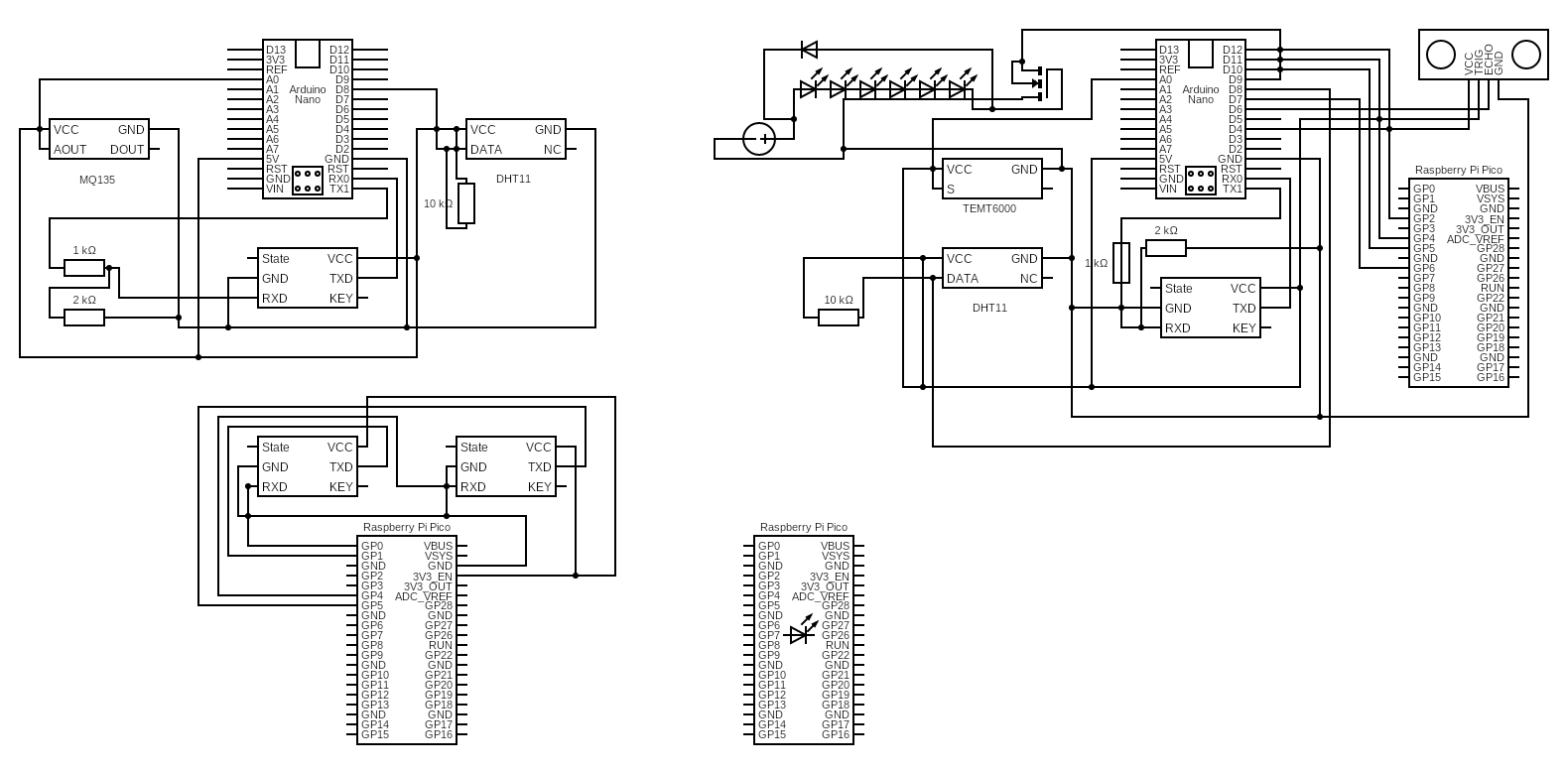
Controllers brief overview:
- Raspberry Pi PicoW. It is a low-cost, high-performance microcontroller board with flexible digital interfaces. It has a RP2040 microcontroller, Dual-core Arm Cortex M0+ processor, flexible clock running up to 133 MHz, 264kB of SRAM, and 2MB of on-board flash memory, Low-power sleep and dormant modes, 26 × multi-function GPIO pins, 2 × SPI, 2 × I2C, 2 × UART, 3 × 12-bit ADC, 16 × controllable PWM channels, Accurate clock and timer on-chip, Temperature sensor, Accelerated floating-point libraries on-chip, 8 × Programmable I/O (PIO) state machines for custom peripheral support. It works on 3V3 levels.
- Arduino Nano. It is microcontroller board based on the Atmega328P. The board has 14 digital input/output pins (6 of which can be used as PWM outputs), 8 analog inputs and a 16Mhz quartz crystal. It works on 5V levels.
- HC-05 Bluetooth Module. It is a small, low-cost device that enables wireless communication between devices using the Bluetooth Protocol. It can operate in both slave and master modes, and is commonly used in projects such as remote control systems, wireless data transfer and wireless sensor networks. It can be easily interfaced with a microcontroller, using the UART protocol. It can be powered from 3.6 to 6 volts, because it comes on breakout board which contains a voltage regulator. However, the logic voltage level of the data pins is 3.3V. Because it is a bluetooth module it can communicate with only one slave/master at once. In order to pair it with another module either as a master or as a slave, we must use AT commands to do so.
Sensors brief overview:
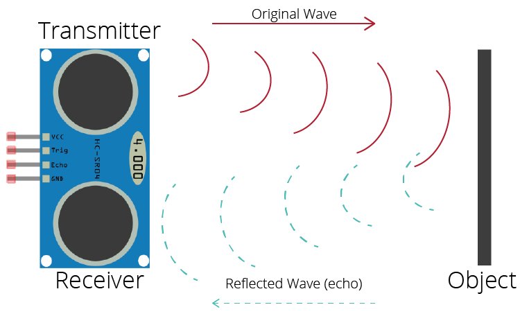
- HC SR04. It's a device that uses ultrasonic waves to measure distance to an object. It transmites high-frequency sounds and measures the time it takes for the sound to bounce back to the sensor, which is then used to calculate the distance to the object. The sensor consists of an ultrasonic transmitter (Trig pin), a receiver (Echo Pin) and a control circuit. It has an operating voltage of 5V and operating current of 15mA.
- DHT11. It's a basic, low cost digital temperature and humidity sensor. It uses a capacitive humidity sensor and a thermistor to measure the surrounding air. The sensor also includes an 8-bit SOIC-14 packaged IC. This IC measures and processes the analog signal using stored calibration coefficients, converts the analog signal to digital, and outputs a digital signal containing the temperature and humidity. The values are provided through a single-wire digital interface, making it easy to interface it with a microcontroller or other controller circuit. DHT11 can measure temperatures from 0°C to 50°C with an accuracy of ±2°C. In addition, the DHT11 sensor can measure relative humidity from 20 to 80% with an accuracy of 5%. It has an operating voltage from 3V to 5V and operating current of maximum 2.5mA.
- TEMT6000. The TEMT6000 is a ambient light sensor which is a small, surface-mount device that detects the intensity of ambient light. It is designed to detect visible light in the range of 390–700 nm, and convert it into an electrical signal output (the S pin). The sensor is based on a phototransistor that changes its electrical resistance based on the amount of light it receives.It is suitable for a variety of applications such as automatic lighting control, display backlight control, and camera light detection. This sensor can handle voltages from both 5V and 3.3V devices.
- MQ135. The MQ135 is a gas sensor that is designed to detect a wide range of gases, including ammonia (NH3), sulfur dioxide (SO2), carbon monoxide (CO), and volatile organic compounds (VOCs) in the air. It is based on a metal oxide semiconductor (MOS) that is sensitive to the target gases. The sensor generates an electrical current that is proportional to the concentration of the target gas. The MQ135 sensor can detect gases in a concentration range between 10 to 1000ppm. It is commonly used in air quality monitoring systems, indoor air quality monitoring, and other applications where the detection of harmful gases is important.
3. Software implementation and the overall logic
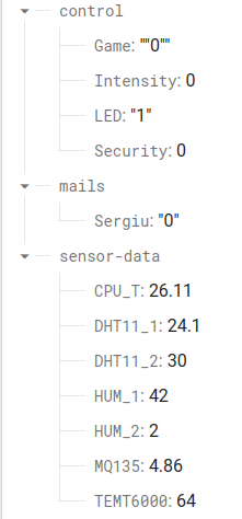
The DataBase used for this project was a RealTimeDataBase from FireBase. The data was structured in 3 categories :
- sensor-data - These represent the data from the sensors. These can not be changed by the user.
- control - These represent the control flags which can be changed by the user using the App. With them we can control the actions of the NANO 2
- mail - These hold the number of unread emails from specific persons(ex: Sergiu)
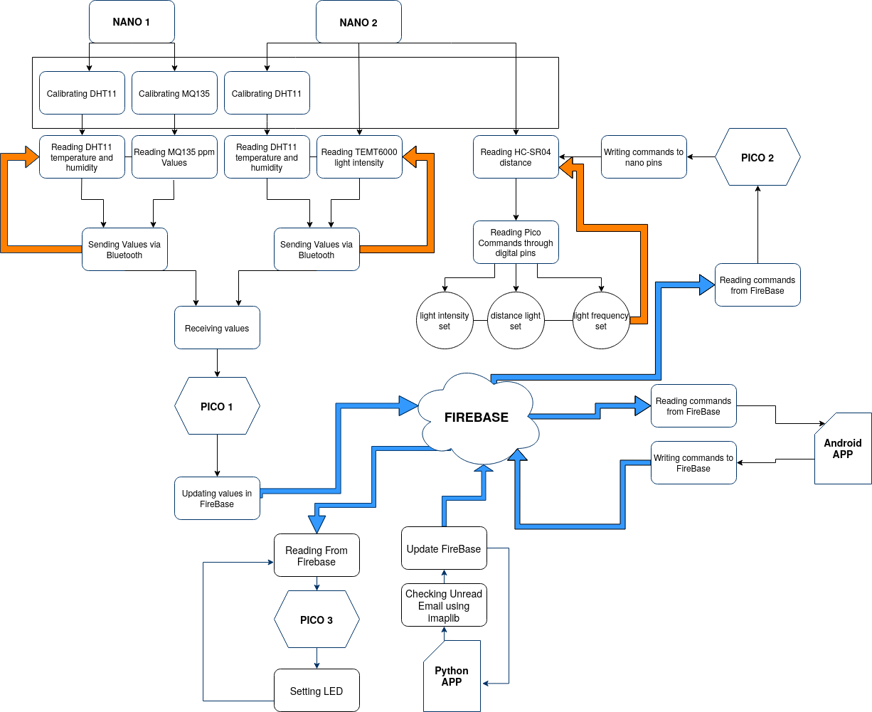
The implementation consists of 6 main parts :
- The monitoring of the first room. The first room which would be the kitchen has the DTH11 and MQ135 sensors installed. Thus, we are monitoring the temperature, humidity and gas levels in the room. After the values are read, they are sent via Bluetooth to the Pico1. For each sensor value I have used 2 bytes, thus sending a series of 8 bytes every 2 seconds after each read.
- The monitoring of the second room. The second room monitors the humidity, temperature and light intensity. Again I am using 2 bytes for each value thus sending 8 bytes to the PICO1 every 2 seconds after each read. Furthermore, the microcontroller also has a ultrasonic sensor and a LED strip connected to it. After reading the commands from the PICO2, it can decide in which mode the LED strip is operated. So far, I can have the LED's lighting up when you are close to them ( thus using the distance sensor ), or have them lighting up and off at different frequencies or intensities.
- Sending data to the Firebase and receiving it with PICO1. The PICO1 receives 8 bytes from both NANOs.Because the PICO has 2 UART interfaces we can easily connect to HC-05 to it, each speaking to a particular NANO. After the values are received we publish them to the FireBase RealTimeDatabase.
- Reading data from the Firebase with the Android App and sending commands. The Android App was made using MIT APP Inventor, and can read the sensor-data values, and also update the control values via the user interface.
- Reading data from the Firebase with PICO2 and sending commands with PICO2. The PICO2 acts as an observer. It check every 1 second if the control values from the DataBase where changed. If they were changed the PICO will alert the NANO and the NANO will execute the specific commands.
- Lighting up when receiveing email with PICO3. I have developed a small program in Python which uses imap to check the number of unread emails from specific persons. The number is then updated in the FireBase. The program is ran from the personal laptop. After that the Pico3 check that number, and it start to blink for number of unread messages. After that it stays on, or off if all the messages were read.
fig.3 Android APP structure. RealTimeDataBase Structure
A little description of the protocol used :
- webSockets. With WebSockets, messages can be pushed at any moment without regard to a previous request by both the server and the client. A few drawbacks with HTTP are resolved by WebSocket, including the bi-directional protocol, full-duplex communication (client and server can speak to each other separately at the same time), and a single TCP connection. Firebase databases' use of WebSockets has a number of restrictions. First of all, the database is the central concept, with realtime synchronization (messaging) as an add-on feature. Only the updates to your database are published to connected clients. This forces you to permanently store even the transient events that need to be streamed to your users, leading to an unnecessary increase in storage costs. An example of transient messages in a chat app scenario would be indicators that others are typing – events that occur frequently but have zero need for permanent storage. Speaking of scalability, you can scale the Firebase databases up to a point. We’ve previously mentioned that an instance of the Firebase Realtime Database has a limit of 200.000 concurrent WebSocket connections. You can scale beyond this limit by sharding your data across multiple instances. However, it’s worth bearing in mind that sharding can become a significant challenge that leads to increased complexity and management overhead.\\
- iMap. IMAP serves as a middleman between the email server and email client as an incoming email protocol. When users read an email using IMAP, they read them off the server. The email isn't really downloaded or kept on their local device. This means that users can access the email from anywhere in the world using a variety of devices because it is not tied to a particular device.
4. Demonstration
5. Difficulties
There were many difficult parts in this project. Firstly I wanted to use NRF24l01 radio modules instead of the HC-05 modules, because they are more versatile. Unfortunately I did not manage to configure them correctly. After that, I had to learn the AT commands and how to configure the HC-05 modules. These was harder than it seemed due to many faulty wire connections I had on my breadboard. There was also some learning curve trying to understand how work with the Picos, APP inventor and the FireBase. I met various connectivity issues and the Picos ran of out RAM. Again I had many problems with my breadboards with many faulty connections and I needed to do various hardware debugs using my multimeter. Moreover, the Picos were not as fast as I expected, and it took them too much time to read or write to the database.
6. Overlook and conclusion
The proposed project has reached its goal mainly. I managed to do an IoT level 5 based system. I learned how to design and think such system, how to work with databases and what should I take into consideration when making multiple nodes communicating with each other. However, the many difficulties I encountered stopped this project from becoming fully functional. Too many Picos connected to the internet means more exposure to hacking, and slow performing times sometimes takes from the usefulness. All in all, it was a great learning experience and I am looking forward to improve this system in order to be safely used in any home.
7. Resources
https://www.raspberrypi.com/documentation/microcontrollers/raspberry-pi-pico.html
https://lastminuteengineers.com/arduino-sr04-ultrasonic-sensor-tutorial/
https://lastminuteengineers.com/dht11-dht22-arduino-tutorial/
https://learn.sparkfun.com/tutorials/temt6000-ambient-light-sensor-hookup-guide/all
https://howtomechatronics.com/tutorials/arduino/how-to-configure-pair-two-hc-05-bluetooth-module-master-slave-commands/
http://helloraspberrypi.blogspot.com/2021/02/pair-hc-05-master-slave-using-raspberry.html
https://electronicsprojectshub.com/setup-dht11-sensor-with-arduino/
https://ably.com/topic/firebase-vs-websocket
https://www.techtarget.com/whatis/definition/IMAP-Internet-Message-Access-Protocol

