Security System with ESP32
author Dinu Diana-Gabriela ACES 2021
1. Project Objective
The purpose of the project is to create a smart security system.
The security alarm does not provide audio feedback when movement is detected. The owner can turn the alarm on and off without physical access to the system, but rather via a web page. When turned on, if the security system detects movement it will notify the owner with an E-mail and will update the web page as well.
2. Project Description
The Security System consists of:
- A web Server - it will allow the user to turn the system on and off, and to view the state of the system in real time (if motion is detected or not)
- E-mail notifications - the user will receive E-mail notifications each time the security alarm is triggered by movement
- Motion detection system - This is the physical part of the project, which will contain a PIR sensor which will detect the physical movement in the proximity of the system. The System will also contain 2 LEDs for visual feedback of the state of the system, one for the System State (on or off) and one for the motion sensor (if motion is detected or not)
3. Hardware Description
The hardware consists of:
- ESP32 Development Board - The ESP32 Development Board is a system development board powered by ESP-WROOM-32 module. The ESP-WROOM-32 is a powerful and compact module that combines Wi-Fi and Bluetooth to support a wide range of applications that require wireless and internet connectivity [2]. The Wi-fi support, discreet size and price range made it perfect for this application.
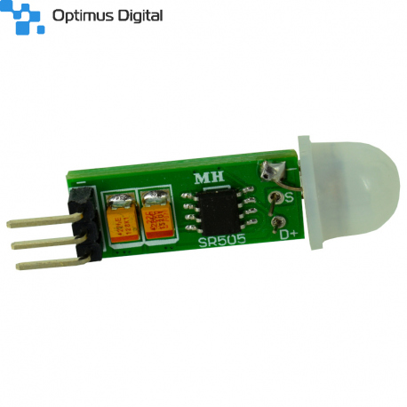
- PIR sensor - A Passive Infrared Sensor was used to detect the movement. It is an electronic sensor that measures infrared light coming from objects in its field of view. This type of sensor is widely used in security alarms. [1] The sensor picked has a delay of 8 seconds between changing its output. It can be powered from the 5V pin of the ESP32 board. It has an output voltage of 3.3V which can be read by the ESP32 board. It can detect movement at a maximum distance of 3m.
- LEDs for visual feedback - the onboard LED of the ESP32 Development board is used for showing that the security system has the motion detection on or off. An external LED is also used to show if the Security System detected movement. In order to use the external LED, an additional resistor is also needed.
Besides the main components mentioned above, a breadboard and wires were also used in the making of this project. The electrical schematic of the project can be seen below. [The diagram was made using circuit.io]
4. Software Description
For software development, the Arduino IDE was used.
Libraries
The main libraries used are:
- WiFi.h - used to connect to the Wifi Network
- ESP32_MailClient.h - library used to connect to a SMTP (Simple Mail Transfer Protocol) Server for sending emails.
- SPIFFS.h - The SPIFFS (Serial Peripheral Interface Flash File System) library was used for saving images to the internal flash without using any external memories. SPIFFS is a file system used to split the flash of the ESP32 board in two regions, allowing the storage of files in the new region created.
- time.h - used for getting accurate information on the time that passed between events and for getting local time information.
- ESPAsyncWebServer.h and AsyncTCP.h - These libraries are used for creating the asynchronous Web Page. This allows for image usage and changing data on the page (for the motion feedback) without refreshing the page.
Functionality Breakdown
The main functionality of the page is sketched in the diagram below.
When the program is uploaded to the board, it will start the setup process. During the setup it will initialize the board, the GPIO pins, it will connect to the Wi-fi Network and setup the web server. It will also get the local time, this is used for serial monitor debug.
After the setup is complete, regarding the Web server the following things will happen:
- The Web page created at the board's IP address will monitor the switch state (which will be changed from the browser). On changing the switch state, the onboard LED (showing the Security System state - on or off) will change its state and an internal variable, which is used to block functionality when the Security System is off, will also change its value.
- The Web Page will also request the state of the motion detection every 9.9seconds.
- When refreshed the page will request the data from the board.
In parallel, the following things will happen, as per the diagram above:
- The external LED is turned off if no previous motion was detected.
- When an the state of the PIR sensor output changes to high, an interrupt will appear. This interrupt will start the detectsMovement() function. When this function is called the system knows there is motion detected.
- This function checks that the Security System is turned ON before doing anything. If the system is OFF, nothing is done. If the system is on the external LED will be turned ON to signal movement. It will also connect to SMTP server given and will send an E-mail from teh borad's email to the user's email.
- The program is set to wait for 10 seconds after a motion detection is made. This is partly because of the sensor delay of 8 seconds, and to limit the emails received. This time period can be increased. After these 10 seconds. the external LED is turned OFF and the cycle happens every time an interrupt (rising edge of the PIR sensor output) happens.
Code Breakdown
The Web page
The HTML code for teh web page is inserted below. Part of the code is edited out for saving space in the documentation, as it is not important functionality wise. Below we can see the placeholders for the button which will turn the system on and OFF and also for the live feedback of the motion status (if there is movement or not). The IDs for these placeholders and how they should be interpreted is mentioned in the script part of the page. The setInterval function will be called each 9.9 seconds to interrogate the state of the motions sensor. This time was chosen because the state machine is made to change the internal state on every 10 seconds, therefore sampling this every 9.9 ensures we will get a match for the least number of interrogations.
<body>
  <h2>ESP Security System</h2><br>
  <img src="secure"
    width="90"
    height="90"/><br>
  %BUTTONPLACEHOLDER%<br>
  <h3>Sensor Value:<span id="sensors">%MOTIONPLACEHOLDER%</span></h3><br>
<script>
function toggleCheckbox(element) {
  var xhr = new XMLHttpRequest();
  if(element.checked){
    xhr.open("GET", "/update?output="+element.id+"&state=1", true);
  } else {
    xhr.open("GET", "/update?output="+element.id+"&state=0", true);
  }
  xhr.send();
}
setInterval(function ( ) {
  var xhttp = new XMLHttpRequest();
  xhttp.onreadystatechange = function() {
    if (this.readyState == 4 && this.status == 200) {
      document.getElementById("sensors").innerHTML = this.responseText;
    }
  };
  xhttp.open("GET", "/sensors", true);
  xhttp.send();
}, 9900 ) ;
</script>
In order to replace the placeholders, the processor function was created. In here we define the html code structure to be replaced in the html page, based on the IDs and the information received/requested.
String processor(const String& var){
  if(var == "BUTTONPLACEHOLDER"){
    String buttons = "";
    //change the state of the onboard LED (2)
    buttons += "<h4>System State OFF/ON</h4><label class=\"switch\"><input type=\"checkbox\" onchange=\"toggleCheckbox(this)\" id=\"2\" " + outputState(2) + "><span class=\"slider\"></span></label>";
    return buttons;
  }
  if(var == "MOTIONPLACEHOLDER"){
    String buttons = "";
    if(startTimer == true){
      buttons += "<h4 style=\"color:red;\">MOTION DETECTED!</h4>";
    } else {
      buttons += "<h4>Motion not detected</h4>";
    }
    return buttons;
  }
  return String();
}
In order to initialize the web page, the following code was placed in the setup() function to initialize the motion state message and the state of the switch.
server.on("/sensors", HTTP_GET, [] (AsyncWebServerRequest *request) {
    if(startTimer == true){
      request->send(200, "text/html", "<h4 style=\"color:red;\">MOTION DETECTED!</h4>");
    } else {
      request->send(200, "text/html", "<h4>Motion not detected</h4>");
    }
  });

// Send a GET request to <ESP_IP>/update?output=<inputMessage1>&state=<inputMessage2>
  server.on("/update", HTTP_GET, [] (AsyncWebServerRequest *request) {
    String inputMessage1;
    String inputMessage2;
    // GET input1 value on <ESP_IP>/update?output=<inputMessage1>&state=<inputMessage2>
    if (request->hasParam(PARAM_INPUT_1) && request->hasParam(PARAM_INPUT_2)) {
      inputMessage1 = request->getParam(PARAM_INPUT_1)->value();
      inputMessage2 = request->getParam(PARAM_INPUT_2)->value();
      digitalWrite(inputMessage1.toInt(), inputMessage2.toInt());
    } else {
      inputMessage1 = "No message sent";
      inputMessage2 = "No message sent";
    }

    if(inputMessage2 == "0"){
      Serial.print("Security system is OFF \n\n");
      Sec_Sys_State = "off";
    } else { if(inputMessage2 == "1"){
      Serial.print("Security system is ON \n\n");
      Sec_Sys_State = "on";
    }}
    request->send(200, "text/plain", "OK");
  });
In order to place an image in the web page, SPIFFS was used. The image is uploaded to the board before uploading the code to the board. The image is placed in a separate folder names data.
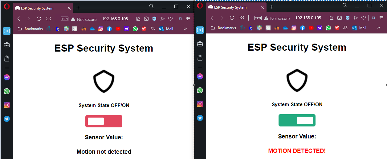
When all of this is put together, the web page will look like in the screenshots below.
Side by side image of web page when the system is OFF, and when the system was turned ON and motion was detected.
Motion Detection
In order to detect the input of the PIR sensor and detect the moments where movement happens, an interrupt was attached to a positive edge of the pin where the output of the PIR sensor was connected. This can be seen in the code selection below.
// Checks if motion was detected, sets LED HIGH and starts a timer
void IRAM_ATTR detectsMovement() {
  if(Sec_Sys_State == "on"){
    Serial.println("MOVEMENT DETECTED!!!");
    digitalWrite(LED, HIGH);
    startTimer = true;
    lastTrigger = millis();
    printLocalTime();
    MOVEMENT = true;
  }
}

[...]

void setup(){
[...]
  // PIR Motion Sensor mode INPUT_PULLUP
  pinMode(motionSensor, INPUT_PULLUP);
  // Set motionSensor pin as interrupt, assign interrupt function and set RISING mode
  attachInterrupt(digitalPinToInterrupt(motionSensor), detectsMovement, RISING);
[...]
}
5. Issues and solutions
There have been a few issues met in the making of this project.
The first problem was related to the type of web page. In the beginning a synchronous web page was used. This did not allow the usage of images. In order to fix this and give more information in the web page, a asynchronous type web page was used.
There have also been a few issues with the sensor. The main problem was receiving false movement detection. This was because of small crowded spaces, or my presence near the sensor, but most probably is was due to the monitors, which were placed in close proximity of the sensor. The monitors do emit some amount of IR light, so this might have been messing with the PIR sensor. This is not a real issue in real life applications, but it was troubling when the demo was filmed, as the system needed to be close to a monitor in order to show the web page, received emails and debug information. This was solved in the demo by inclining the board of the system, slightly away from the monitor.
Overall I would say the challenges have been surpassed and that the project works well.
6. Conclusions
In conclusion, the project successfully implements a security system which can alert the user of unexpected movement close to the system. The project shows how smart systems can be implemented in our day to day life.
Despite the challenges that appeared along the way, this project was helpful in teaching us how we can implement our own smart systems without spending a fortune.
Bibliography
Documentation sources
1. Passive infrared sensor - Wikipedia
3. Electrical schematic tool - circuito.io
4. State machine diagram - draw.io
Components
1. Cleste
Libraries
2. AsyncTCP and ESPAsyncWebServer
4. Attaching interrupt routines
Download the Source code


