This is an old revision of the document!
Safe Deposit Box
Diana-Alexandra Predescu - ACES 2021
Project description
The purpose of this project is to simulate a safe deposit box that can be remotely controlled through a Web server. This application can easily be integrated into the concept of smart house. For this project I will only focus on the remotely controlled part.
In this project, the box can only be opened/closed with buttons from a Web server, after connecting to Wi-fi. With the help of two sensors, the application can figure out when something isn’t right and change the status of the box in the Web server. If the door is broken without opening it from the Web page, or it detects accelerated movement the system alerts the user with a status message in the Web server. All the above was possible by interfacing ESP 32 microcontroller to the external modules.
Hardware description
The modules used to achieve the functionality mentioned above are:
- ESP-WROOM-32 Board: is the MCU which controls the system, handles the web page and ensures the interface with the external modules. The board was programmed using Arduino IDE;
- FXLN8371 Accelerometer: the module measures the rate of change of the velocity of an object in G-forces(g). The FXLN8371Q offers an analog interface, which measures acceleration from the variation between ground and power supply voltage. The voltage level from the output pins can be converted with an ADC to a binary value to be interpreted by the processor. In order to offer accuracy, the accelerometer had to be calibrated first. It is connected to the 3.3V power supply coming from MCU, XOUT to GPIO34, YOUT to GPIO35 and ZOUT to GPIO32.
- Optic sensor: a sensor based on an infrared light from a LED which illuminates a phototransistor. If an object is placed between the LED and the phototransistor, the LED light turns off. This will check if the door is closed. The module is powered from 5V and the signal pin is connected to GPIO19.
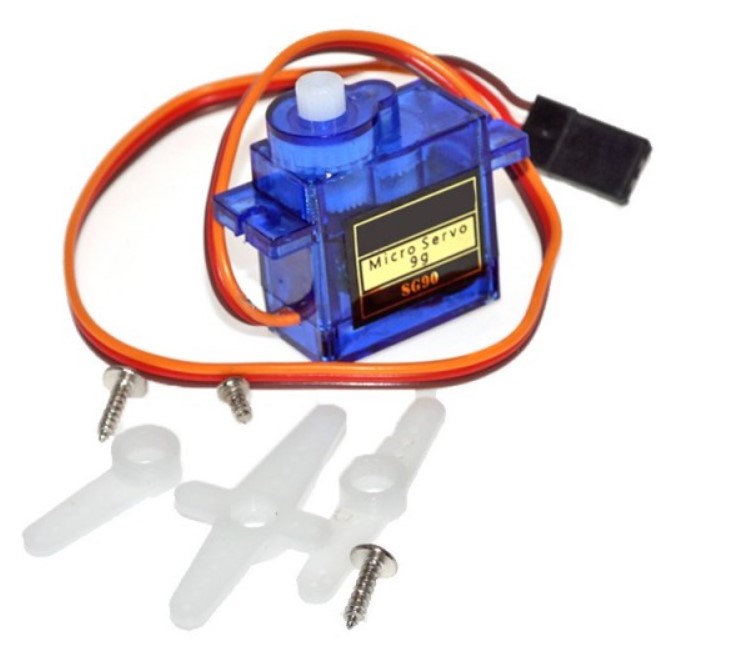
- SG90 servo motor: A simple servo which simulates when the door is opened/closed, making it rotate from 0° to 180° and back. The servo is connected to 5V and the PWM controlling signal to GPIO18.
The electrical schematic of the circuit and the breadboard implementation can be found below:


