
This is an old revision of the document!
Mini-plotter
Introduction
This project is an interactive, standalone CNC-style drawing machine powered by the ATmega328P microcontroller. It translates user inputs from a resistive touch panel or pre-loaded data into precise mechanical motion using NEMA 17 stepper motors. The system features a built-in UI displayed on an ILI9486 LCD, allowing the user to select between distinct operating modes via a potentiometer.
- Purpose: The primary goal is to design a versatile embedded system that handles multi-peripheral integration; specifically ADC processing for touch and analog inputs, SPI communication for external storage, and precise timing for stepper motor control.
- The idea: The project was inspired by the desire to build a simpler version of a CNC machine that can be easy to modify, operate and calibrate, but without compromising the features and complexity of the software.
- Utility: For the developers, it provides deep, hands-on experience with microcontroller peripheral management, memory constraints, and motion control logic. For users, it serves as an intuitive, tactile tool capable of assisting in drawing perfect geometric shapes or automatically replicating complex digital patterns.
General Description
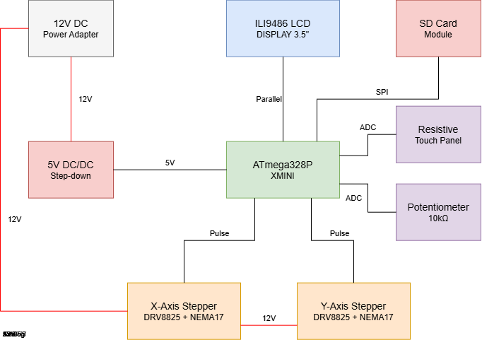
Mini-Plotter is an automated drawing system based on the ATmega328P-XMINI. The system operates as a closed-loop interface where user input is captured via a resistive touch screen or an SD card and translated into physical motion through two NEMA 17 stepper motors. The project logic is divided into three functional layers:
- Input Acquisition: Captures analog coordinates (via Resistive Touch) and menu selection (via Potentiometer) or digital data (via SD Card).
- Processing & Control: The MCU executes state-machine logic to handle three modes:
- Freehand
- Shape Correction (algorithmic smoothing)
- SD File Execution
- Output Execution: Real-time visual feedback on the ILI9486 LCD and high-precision motor control via DRV8825 drivers.
Block Diagram
Hardware Design
Component List
| Component | Specification | Role/Connection |
|---|---|---|
| ATmega328P-XMINI | 8-bit Microcontroller | Central processing and logic control |
| NEMA 17 Stepper | 1.8° Step Angle, High Torque | Dual-axis (X-Y) mechanical movement |
| DRV8825 Driver | Up to 1/32 microstepping | Current control for stepper motors |
| ILI9486 LCD Module | 3.5” TFT with Integrated SD Slot | UI display and data storage (SPI Interface) |
| Resistive Touch | 4-Wire Overlay | Coordinate input for manual drawing |
| Potentiometer | 10k Ohm Rotary | Menu navigation and mode selection |
| Power Supply | 12V DC / 2A | Powering motors and logic (via step-down) |
Hardware Implementation Status
The hardware architecture of the mini-plotter has been fully designed, verified, and mapped. The implementation is executed in two concurrent phases:
- Power and Motion Subsystems (Fully Implemented): The 12V to 5V DC/DC step-down regulation circuit, the dual DRV8825 stepper driver networks (including electrolytic noise-decoupling capacitors), and the NEMA 17 physical connections are completed and fully operational.
- Control and Display Interfaces (Schematic Level / Pending Integration): The 8-bit parallel LCD interface and SPI SD card slots are fully routed at the schematic level using optimized pin layouts to bypass the ATmega328P's IO limitations. Physical wiring of the display will follow the motion testing phase.
Pin Mapping & Justification
Due to the high number of peripherals required by this project (2 stepper drivers, an 8-bit parallel display, an SPI SD card reader, a touch panel, and a navigation potentiometer), the ATmega328P's pin map is utilized at 100% capacity.
To achieve this without using external multiplexers or IO expanders, several hardware-level optimizations were implemented:
| Component | Pin Name | MCU Pin | Type | Technical Justification |
|---|---|---|---|---|
| X-Axis Driver (A1) | STEP | PD2 | Digital Out | Dedicated hardware pin for step pulses. |
| DIR | PD3 | Digital Out | Direction control logic signal. | |
| Y-Axis Driver (A2) | STEP | PD4 | Digital Out | Dedicated hardware pin for step pulses. |
| DIR | PD5 | Digital Out | Direction control logic signal. | |
| SD Card Module | SD_SS | PB2 | Digital Out | Dedicated Slave Select line for SPI. |
| SD_DI (MOSI) | PB3 | Hardware SPI | Master Out Slave In - standard high-speed data line. | |
| SD_DO (MISO) | PB4 | Hardware SPI | Master In Slave Out - standard high-speed data line. | |
| SD_SCK | PB5 | Hardware SPI | Serial Clock line to synchronize data transfers. | |
| ILI9486 LCD (Control) | LCD_RST | PC4 | Digital Out | System reset line for the display controller. |
| LCD_CS | PC3 | Digital Out | Chip Select line for the parallel display bus. | |
| LCD_RS | PC2 | Digital Out | Register Select (Commands vs. Pixel Data). | |
| LCD_WR | PC1 | Digital Out | Write strobe signal clocking the 8-bit bus. | |
| LCD_RD | +5V | Hardwired | Optimization: Permanently tied to High. The MCU only writes data; reading from the display is disabled to save 1 digital GPIO pin. | |
| ILI9486 LCD (Data) | LCD_D0 - D1 | PD0 - PD1 | Parallel Bus | Lower 2 bits of the 8-bit data bus. |
| LCD_D2 - D3 | PD6 - PD7 | Parallel Bus | Middle bits of the 8-bit data bus. | |
| LCD_D4 - D5 | PB0 - PB1 | Parallel Bus | Higher bits of the 8-bit data bus. | |
| LCD_D6 - D7 | PC0 - PC5 | Parallel Bus | Remaining bits routing the full parallel byte. | |
| Peripherals | Potentiometer | ADC6 | Analog In | Optimization: Connected to a dedicated analog-only pin, saving general-purpose digital IO pins. |
| Touch Panel | ADC7 | Analog In | Connected to the second analog-only input channel. |
Electrical Schematic & Explanations
The circuit diagram is structurally grouped into three distinct functional blocks to isolate high-power inductive loads from sensitive logic electronics:
1. Power Supply and Voltage Regulation
The main system power is provided by an external 12V DC / 2A adapter connected through a DC Barrel Jack (J1).
- The 12V Rail powers the motor supply pins (`VMOT`) of both DRV8825 stepper drivers directly.
- An LM2596S-5 buck converter is deployed to regulate the 12V down to a stable 5V rail. This buck converter provides high efficiency under step-down conditions, preventing thermal issues.
- A 100nF ceramic capacitor is placed close to the microcontroller's `VCC` and `AVCC` pins to filter out high-frequency switching noise generated by the buck converter.
2. Stepper Controller Subsystem
Two Pololu DRV8825 breakout boards control the NEMA 17 stepper motors.
- Voltage Spike Protection: A 100µF electrolytic decoupling capacitor is placed in parallel across `VMOT` and `GND` right at the entrance of each driver board. Without these capacitors, the inductive energy/back-EMF from the motor coils could create destructive voltage spikes exceeding the driver's absolute maximum ratings.
- Driver Activation: The `RESET` and `SLEEP` pins of each driver are jumpered together locally to force the driver IC out of standby mode into an active state without wasting MCU control lines.
3. Display & SD Card Interface
The display block handles the routing for the 3.5” TFT LCD Shield. It separates the high-volume display pixel transfers onto an 8-bit parallel topology while routing the SD Card operations through the standardized hardware SPI pins (`MOSI`, `MISO`, `SCK`).
Hardware Assembly & Proof of Functionality


