
This is an old revision of the document!
ARGB PC Fan Controller with Wireless Remote
1. Introduction
The project represents an intelligent and independent system for controlling the cooling and lighting (ARGB) inside a PC case. It is based on a two-node architecture that communicates wirelessly via Wi-Fi protocol, eliminating the need for long cables and bloatware software installed on the operating system.
- Monitoring internal PC temperature.
- Automatic/manual RPM (PWM) control.
- Managing ARGB visual effects.
- Remote control interface.
2. Project Description (What it does)
The system is divided into two main units working together:
A. Central Unit (The Controller)
It is the heart of the system, implemented on a T-HMI (ESP32-S3) module with an integrated LCD display.
- DHT22 Sensor: Constantly reads the case temperature.
- ARGB Control: Manages the colors and modes of the Thermalright fan.
- Real-time Display: Projects the RPM, temperature, and current mode on the screen.
B. The Remote (Control Unit)
Built on an ATmega328P Xplained Mini board connected to an ESP-01S module.
- Features an expansion board with 5 buttons.
- Allows changing operating modes and speed remotely.
- Externally powered for total portability.
3. Operating Modes
- Auto Mode (Default):
- The system automatically adjusts the fan speed using a temperature curve.
- For every 5°C threshold reached, the fan speed progressively increases or decreases to maintain the balance between cooling and noise.
- Manual Mode:
- The user takes full control via the remote.
- Dedicated buttons can be used to increase or decrease the speed regardless of the read temperature.
4. Project Purpose and Motivation
What is its purpose?
The primary purpose is to provide a user-friendly hardware interface that allows users to easily monitor and control fan speeds and ARGB lighting. While connecting a fan directly to the motherboard provides basic cooling, this project focuses on delivering accessible, real-time control without relying on proprietary software. It essentially protects the user from the risk of losing manufacturer support (abandonware), or turning into resource-heavy bloatware over time.
Origin of the Idea
The idea stemmed from the frustration caused by software dependency and forced firmware updates of commercial products, which often break functionality or add unnecessary background processes. I wanted a hardware-level “Plug & Play” device that guarantees longevity and provides clear information on a physical display, completely independent of the PC's software ecosystem.
Usefulness for users
- For me: It gives me precise, physical control and immediate visual monitoring over my PC's thermal state and aesthetics without tabbing out of applications or games.
- For others: The same as above, but also Future-Proof & No Obsolescence: Since it doesn't require a dedicated app, it will never lose functionality due to lack of software support from a manufacturer.
- OS Independence: Works on Windows, Linux, or macOS seamlessly, without requiring any drivers.
- Zero Resource Consumption: Does not load the PC's processor or RAM (crucial for gamers or heavy-duty tasks).
- Customization: While the interface is simple, it ofers all the customization a normal user needs.
5. Hardware Components Used
- Microcontrollers: ESP32-S3 (Central unit) and ATmega328P Xplained Mini (Remote).
- Remote Communication: ESP8266 ESP-01S Wi-Fi module.
- Sensor: AM2302 (DHT22) for temperature and humidity.
- Actuator: Thermalright C12CW-S ARGB Fan.
- Interface: LCD Display (integrated on T-HMI) and a 5-button module.
- Power Management:
- Remote: External battery and an AMS1117-3.3V voltage regulator (to step down voltage for the Wi-Fi module).
- Controller: Laptop USB-C connection (5V for the ESP32 logic and ARGB LEDs), a 12V 1A Wall Adapter, and a DC Screw Terminal (for the fan motor).
Block Schema
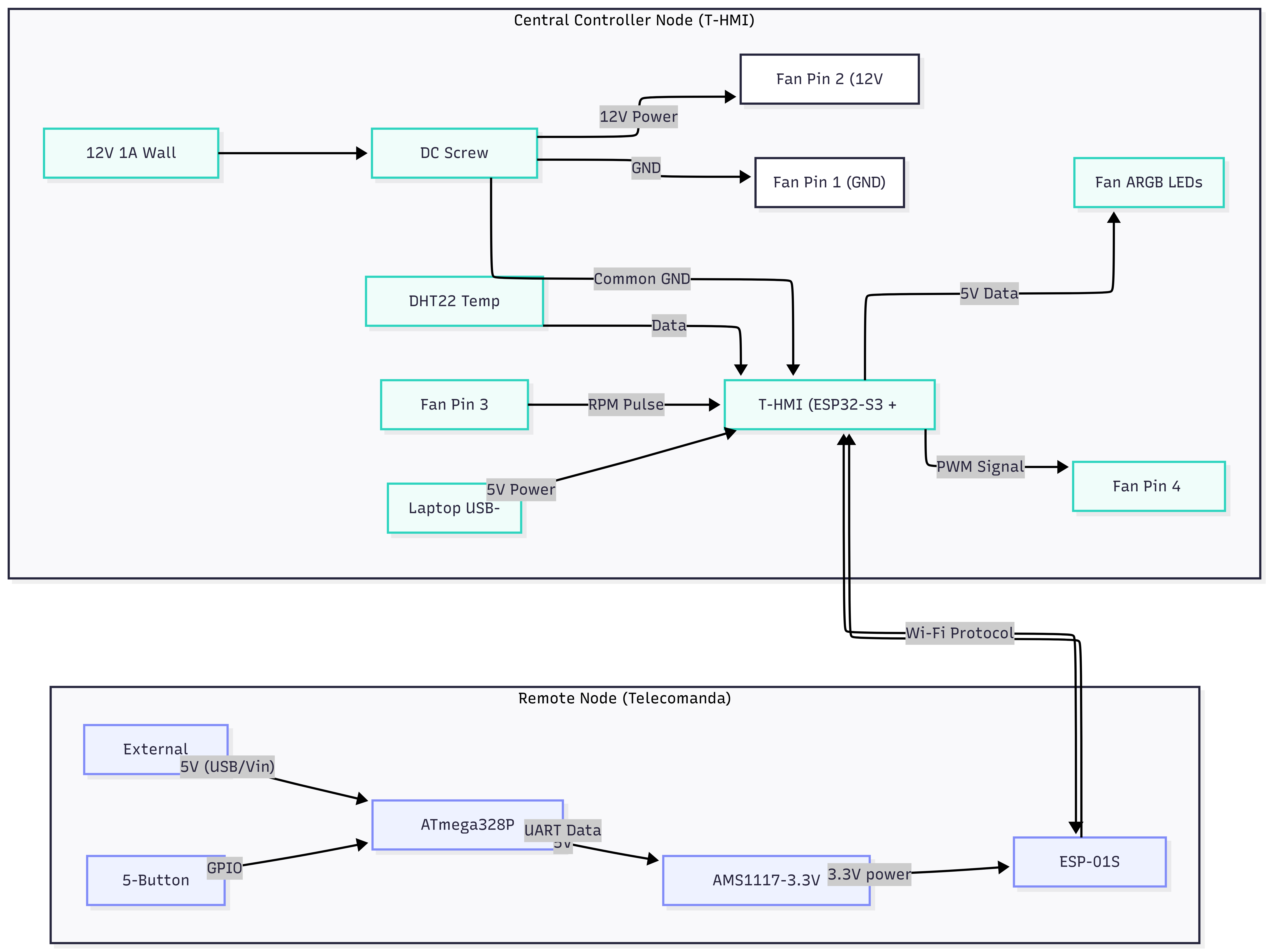
Hardware Design
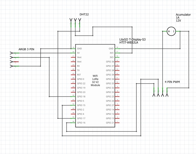 Schema electrica telecomanda
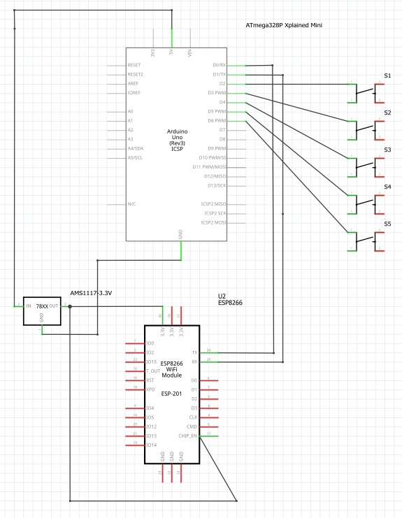
Hardware Pin Configuration
1. Remote Node (Telecomanda)
The Remote Node utilizes an ATmega328P microcontroller communicating with an ESP8266 (ESP-201 breakout format) Wi-Fi module. Voltage regulation from 5V to 3.3V is handled by an AMS1117-3.3V linear regulator.
1.1 ATmega328P Pin Mapping
| ATmega328P Pin (Arduino Label) | Connected To | Component / Signal Description |
|---|---|---|
| PD0 (D0/RX) | ESP8266 TX | UART Serial Data Receive |
| PD1 (D1/TX) | ESP8266 RX | UART Serial Data Transmit |
| PD2 (D2) | Button S1 (Pin 1) | Digital Input for Button 1 (Internal Pull-up) |
| PD3 (D3) | Button S2 (Pin 1) | Digital Input for Button 2 (Internal Pull-up) |
| PD4 (D4) | Button S3 (Pin 1) | Digital Input for Button 3 (Internal Pull-up) |
| PD5 (D5) | Button S4 (Pin 1) | Digital Input for Button 4 (Internal Pull-up) |
| PD6 (D6) | Button S5 (Pin 1) | Digital Input for Button 5 (Internal Pull-up) |
| 5V | AMS1117 IN (Pin 2) | 5V DC Power Source Output from USB |
| GND | Main GND Rail | Common System Ground Reference |
1.2 ESP8266 Wi-Fi Module (ESP-201)
| ESP8266 Pin | Connected To | Signal Description |
|---|---|---|
| TX | ATmega328P PD0 (D0/RX) | Serial Transmit Data |
| RX | ATmega328P PD1 (D1/TX) | Serial Receive Data |
| 3.3V | AMS1117 OUT (Pin 3) | Regulated 3.3V Power Input |
| CHIP_EN | AMS1117 OUT (Pin 3) | Chip Enable Pin (Pulled HIGH to activate) |
| GND | Main GND Rail | System Ground Reference |
1.3 AMS1117-3.3V Voltage Regulator
| AMS1117 Pin | Connected To | Function |
|---|---|---|
| IN (Pin 2) | ATmega328P 5V | 5V DC Input from Microcontroller |
| OUT (Pin 3) | ESP8266 3.3V & CHIP_EN | 3.3V Regulated Output (Max 800mA) |
| GND (Pin 1) | Main GND Rail | System Ground Reference |
1.4 Input Buttons (S1 - S5)
| Button Component | Pin 1 (Green Side) | Pin 2 (Red Side) |
|---|---|---|
| S1 | ATmega328P PD2 (D2) | Main GND Rail |
| S2 | ATmega328P PD3 (D3) | Main GND Rail |
| S3 | ATmega328P PD4 (D4) | Main GND Rail |
| S4 | ATmega328P PD5 (D5) | Main GND Rail |
| S5 | ATmega328P PD6 (D6) | Main GND Rail |
2. Controller Node
The Controller Node is based on the WiFi LoRa 32 V2 Module. It interfaces with an Addressable RGB LED (ARGB) strip, a DHT22 environment sensor, and a 4-pin PWM fan powered by an external 12V accumulator.
2.1 Microcontroller Pin Mapping
| Module Pin / GPIO | Connected To | Component / Signal Description |
|---|---|---|
| 5V (Pin 20) | ARGB Pin 2 | 5V VCC Power Output for LED Strip |
| 3V3 (Pin 16 / 17) | DHT22 Pin 1 | 3.3V VCC Power Output for Sensor |
| GND (Pin 18 / 19) | System GND Rail | Shared Reference Ground |
| GPIO 16 (Pin 36) | 4 PIN PWM Pin 1 | Fan Control / Tachometer / PWM Output |
| GPIO 21 (Pin 1) | 4 PIN PWM Pin 2 | Fan Control / PWM / Tachometer Output |
| GPIO 17 (Pin 35) | DHT22 Pin 2 | DHT22 Data Signal (Bidirectional) |
| GPIO 18 (Pin 30) | ARGB Pin 4 | ARGB LED Data Signal Output |
2.2 Peripheral Devices Connectivity
DHT22 Sensor
| Sensor Pin | Connected To | Description |
|---|---|---|
| Pin 1 | Module 3V3 | Power Supply Input |
| Pin 2 | Module GPIO 17 | Data Signal Line |
| Pin 4 | Module GND | Ground Reference |
ARGB 3-PIN Connector
| Connector Pin | Connected To | Description |
|---|---|---|
| Pin 1 | System GND | Ground |
| Pin 2 | Module 5V | 5V DC Power Supply |
| Pin 3 | Unused | Not Connected |
| Pin 4 | Module GPIO 18 | Data Signal Line |
4-PIN PWM Fan Header
| Header Pin | Connected To | Description |
|---|---|---|
| Pin 1 | Module GPIO 16 | Control/Feedback Signal 1 |
| Pin 2 | Module GPIO 21 | Control/Feedback Signal 2 |
| Pin 3 | Accumulator (-) / GND | Ground Return Line |
| Pin 4 | Accumulator (+) | +12V Dedicated Power Line |
External Power (Accumulator)
| Terminal | Connected To | Purpose |
|---|---|---|
| Positive (+) | 4 PIN PWM Pin 4 | High-power +12V Supply for the Fan |
| Negative (-) | System GND Rail | Common ground loop safety connection |
Software Design
- mediu de dezvoltare (if any) (e.g. AVR Studio, CodeVisionAVR)
- librării şi surse 3rd-party (e.g. Procyon AVRlib)
- algoritmi şi structuri pe care plănuiţi să le implementaţi
- (etapa 3) surse şi funcţii implementate
Rezultate Obţinute
Concluzii
Download
 .
.
Fişierele se încarcă pe wiki folosind facilitatea Add Images or other files. Namespace-ul în care se încarcă fişierele este de tipul :pm:prj20??:c? sau :pm:prj20??:c?:nume_student (dacă este cazul). Exemplu: Dumitru Alin, 331CC → :pm:prj2009:cc:dumitru_alin.
Jurnal
Bibliografie/Resurse


