
This is an old revision of the document!
Machine Vision Laser Gun - COJOCARU Andrei
Introduction
Key aspects of the project:
- Motion detection:
The system continuously monitors the field of view of the ESP32-CAM module and flags a finded face.
- Laser control:
Using two servomotors, a laser dot is automatically aimed at the detected target.
- Purpose:
Demonstrating the integration of a simple machine vision algorithm on a microcontroller with limited resources and real-time control of the laser’s position.
- Motivation:
Building an accessible, low-cost security solution using off-the-shelf components.
- Applicability:
- Educational prototype in robotics
- Low-cost security system
General description
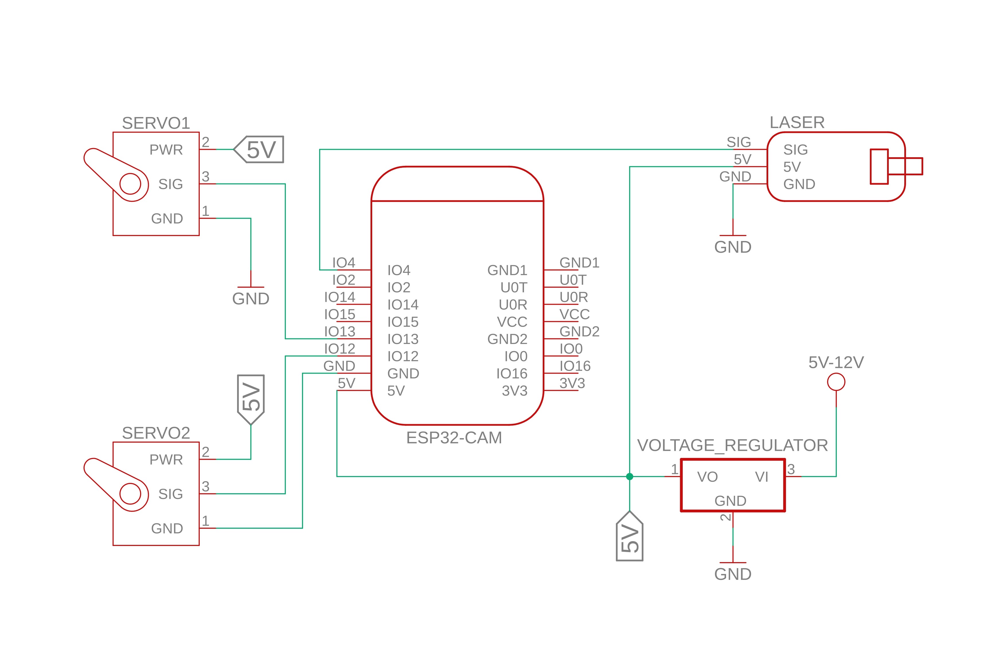
Block Diagram of the system:

Data and signal flow:
- Power supply (5 - 12V) → 5V regulator → ESP32-CAM
- ESP32-CAM: image processing → X/Y coordinate calculation → PWM signal
- Servo 1 (pan) and Servo 2 (tilt): orient the laser mount
- Laser: tracks the target by projecting a dot
Hardware Design
Component List
| Component | Datasheet | Link | Description |
|---|---|---|---|
| ESP32-CAM | Datasheet | ArduShop | Microcontroller |
| Voltage step-down module (AMS1117-3.3) | Datasheet | ArduShop | 5–32 V → 5 V |
| Laser diode module (KY-008) | Datasheet | ArduShop | Laser diode module |
| Servomotors x2 (S3003) | Datasheet | OptimusDigital | Steering servos |

Environment
Development Environment
- Arduino IDE 2.0 with ESP32 support (Espressif plugin)
- Board: AI Thinker ESP32-CAM
3rd-party Libraries
- Espressif ESP32 Camera: esp_camera.h and img_converters.h for camera init and JPEG/RGB565 conversion
- ArduinoWebsockets: WebSocketsServer.h for real-time frame streaming over WebSockets
- Arduino Core WiFi & HTTP: WiFi.h and WebServer.h for AP connection and HTTP control endpoint
- ESP32Servo: for precise PWM servo control
- Framebuffer Graphics: fb_gfx.h for drawing bounding boxes on RGB565 frames
- Espressif ML Face Detection: human_face_detect_msr01.hpp and human_face_detect_mnp01.hpp for two-stage face detection
Face Detection
Face detection algorithm Face detection is implemented in the FaceFinder class:
- Candidate generation with HumanFaceDetectMSR01.
- Refinement with HumanFaceDetectMNP01.
- If any faces remain, the first prediction’s bounding box (x, y, width, height) is extracted and attached to the frame’s dimensions.
- Optionally the box is drawn (or filled) directly into the frame buffer using fb_gfx_drawFastHLine, fb_gfx_drawFastVLine, or fb_gfx_fillRect.
- A boolean found flag is set to true, and the coordinates stored in face.x, face.y, face.w, face.h.
    bool find(uint8_t *buf565, uint16_t width, uint16_t height, bool draw = true, bool fill = false) {
      found = 0;
      frame_w = width;
      frame_h = height;
      {
        HumanFaceDetectMSR01 s1(0.1F, 0.5F, 2, 0.3F);
        HumanFaceDetectMNP01 s2(0.4F, 0.3F, 1);
        std::list<dl::detect::result_t> &candidates = s1.infer((uint16_t *)buf565, {height, width, 3});
        std::list<dl::detect::result_t> &results = s2.infer((uint16_t *)buf565, {height, width, 3}, candidates);

        if (!results.size())
          return 0;

        std::list<dl::detect::result_t>::iterator prediction = results.begin();
        x = (int)prediction->box[0];
        y = (int)prediction->box[1];
        w = (int)prediction->box[2] - x + 1;
        h = (int)prediction->box[3] - y + 1;
        if ((x + w) > width)
          w = width - x;
        if ((y + h) > height)
          h = height - y;
        results.end();
      }

      if (draw) {
        fb_data_t fbd;
        fbd.width = width;
        fbd.height = height;
        fbd.data = buf565;
        fbd.bytes_per_pixel = 2;
        fbd.format = FB_RGB565;
        uint32_t color = 0b1111100000000000;
        if (fill) {
          fb_gfx_fillRect(&fbd, x, y, w, h, color);
        } else {
          fb_gfx_drawFastHLine(&fbd, x, y, w, color);
          fb_gfx_drawFastHLine(&fbd, x, y + h - 1, w, color);
          fb_gfx_drawFastVLine(&fbd, x, y, h, color);
          fb_gfx_drawFastVLine(&fbd, x + w - 1, y, h, color);
        }
      }
      found = 1;
      return 1;
    }
Servo Control
Servo and laser actions are done on the core0:
1. Initialization (initServos()):
- Set PWM period to 50 Hz for both servos.
- Attach X and Y servos on GPIO 13 and 12 with calibration pulses (MIN_PULSE, MAX_PULSE).
- Center servos at midpoints (X_MAX/2, Y_MAX/2).
- Configure laser pin (GPIO 2) as OUTPUT and default LOW.
void initServos() {
  servoX.setPeriodHertz(50);
  servoY.setPeriodHertz(50);
  servoX.attach(SERVO_X_PIN, MIN_PULSE, MAX_PULSE);
  servoY.attach(SERVO_Y_PIN, MIN_PULSE, MAX_PULSE);

  servoX.writeMicroseconds(map(lastCamX, 0, X_MAX, MIN_PULSE, MAX_PULSE));
  servoY.writeMicroseconds(map(lastCamY, 0, Y_MAX, MIN_PULSE, MAX_PULSE));
}
2. Automatic tracking (trackTargetX, trackTargetY):
- Constrain camera coordinates to [0, X_MAX] or [0, Y_MAX].
- Apply a dead-zone threshold (X_THRESHOLD, Y_THRESHOLD) to avoid parasite movements.
- Map camera X/Y to microsecond pulse widths (inverted so left/right or up/down correspond correctly).
- Update servos via writeMicroseconds().
// function to move the pan servo
void trackTargetX(int camX) {
  camX = constrain(camX, 0, X_MAX);
  if (abs(camX - lastCamX) < X_THRESHOLD)
    return;
  lastCamX = camX;
  servoX.writeMicroseconds(map(camX, 0, X_MAX, MAX_PULSE, MIN_PULSE));
}

// fucntion to move the tilt servo
void trackTargetY(int camY) {
  camY = constrain(camY, 0, Y_MAX);
  if (abs(camY - lastCamY) < Y_THRESHOLD)
    return;
  lastCamY = camY;
  servoY.writeMicroseconds(map(camY, 0, Y_MAX, MAX_PULSE, MIN_PULSE));
}
3. Manual control (when trackON == false):
- Flags left, right, up, down trigger fixed-time moves using SERVO_LEFT/SERVO_RIGHT or SERVO_UP/SERVO_DOWN for a duration, then reset to SERVO_STOP.
- shoot flag toggles the laser pin HIGH for a single loop iteration.
// example for moving to the left
if (left) {
        servoX.writeMicroseconds(SERVO_LEFT);
        delay(SERVO_X_MOVE_TIME);
        servoX.writeMicroseconds(SERVO_STOP);
        left = false;

      }
Main application flow
Setup
- Call cam_init(FRAMESIZE_HVGA, PIXFORMAT_JPEG, 10) to start the camera in JPEG mode.
- Connect to the configured WiFi (WIFI_SSID/WIFI_PASS).
- Start an HTTP server on port 80 to set control flags.
- Start a WebSockets server on port 82 for live frame broadcast.
- Launch the core0 task pinned to core 0 for servo and laser control.
void setup() {
  Serial.begin(115200);
  delay(200);
  cam_init(FRAMESIZE_HVGA, PIXFORMAT_JPEG, 10);

  WiFi.mode(WIFI_STA);
  WiFi.begin(AP_SSID, AP_PASS);

  while (WiFi.status() != WL_CONNECTED) {
    delay(500);
    Serial.print(".");
  }

  Serial.print("WIFI IP: ");
  Serial.println(WiFi.localIP());

  server.on("/action", HTTP_GET, handleAction);
  server.begin();
  Serial.println("HTTP server started on port 80");

  ws.begin();
  xTaskCreatePinnedToCore(core0, "Task0", 10000, NULL, 1, &Task0, 0);
}
Main Loop
- Call server.handleClient() and ws.loop() to process incoming HTTP and WebSocket events (e.g. /action?go=left).
- Grab a frame via esp_camera_fb_get(). If no frame, delay and retry.
- If trackON is true:
- Allocate an RGB565 buffer and convert the JPEG frame (jpg2rgb565).
- Run face.find() to detect and draw the bounding box.
- Re-encode to JPEG (fmt2jpg) and broadcast binary data over WebSockets.
- If trackON is false:
- Broadcast the raw JPEG buffer directly.
- Return the frame buffer (esp_camera_fb_return) and delay ~20 ms to regulate frame rate.
void loop() {
  server.handleClient();
  ws.loop();

  // camera frame capture & send
  camera_fb_t *fbj = esp_camera_fb_get();
  if (!fbj) {
    delay(20);
    return;
  }

  if (trackON) {
    // Only convert image & run face-finder when tracking
    uint32_t len = fbj->width * fbj->height * 2;
    uint8_t *buf = (uint8_t *)ps_malloc(len);
    if (buf) {
      bool ok = jpg2rgb565(fbj->buf, fbj->len, buf, JPG_SCALE_NONE);
      if (ok) {
        // swap low->high byte
        for (uint32_t i = 0; i < len; i += 2) {
          uint8_t b = buf[i];
          buf[i] = buf[i + 1];
          buf[i + 1] = b;
        }

        // face detection
        face.find(buf, fbj->width, fbj->height, true, 0);

        // re-encode and broadcast
        if (ws.connectedClients()) {
          size_t jpg_buf_len = 0;
          uint8_t *jpg_buf = nullptr;
          ok = fmt2jpg(buf, len, fbj->width, fbj->height, PIXFORMAT_RGB565, 80, &jpg_buf, &jpg_buf_len);
          if (ok) ws.broadcastBIN(jpg_buf, jpg_buf_len);
          if (jpg_buf) free(jpg_buf);
        }
      }
      free(buf);
    }
  } else {
    // Just stream raw JPEG when not tracking
    if (ws.connectedClients()) {
      ws.broadcastBIN(fbj->buf, fbj->len);
    }
  }

  esp_camera_fb_return(fbj);
  delay(20);
}
Aditional
Conclusions
Download
Bibliography/Resurse
