
Weather Station
Popa Malina
Introduction
A weather station using an Arduino Uno is a project that utilizes various sensors to measure atmospheric conditions such as temperature, humidity, and pressure. The Arduino Uno is a microcontroller board programmed to read and process the data from these sensors and display the information on an LCD display.
General Description
The project typically involves connecting the sensors to the Arduino Uno using jumper wires and programming the board to read the data from each sensor. The temperature sensor measures the ambient temperature, while the humidity sensor measures the amount of moisture in the air. The pressure sensor measures the atmospheric pressure. Once the Arduino Uno has collected the data, it can display the results on an LCD display. The display can show the current temperature, humidity, and pressure readings, as well as additional information such as the time and date.
Block Diagram
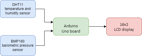
Hardware Design
Components
- Arduino Uno board
- DHT11 temperature and humidity sensor
- BMP180 barometric pressure sensor
- 16×2 LCD display
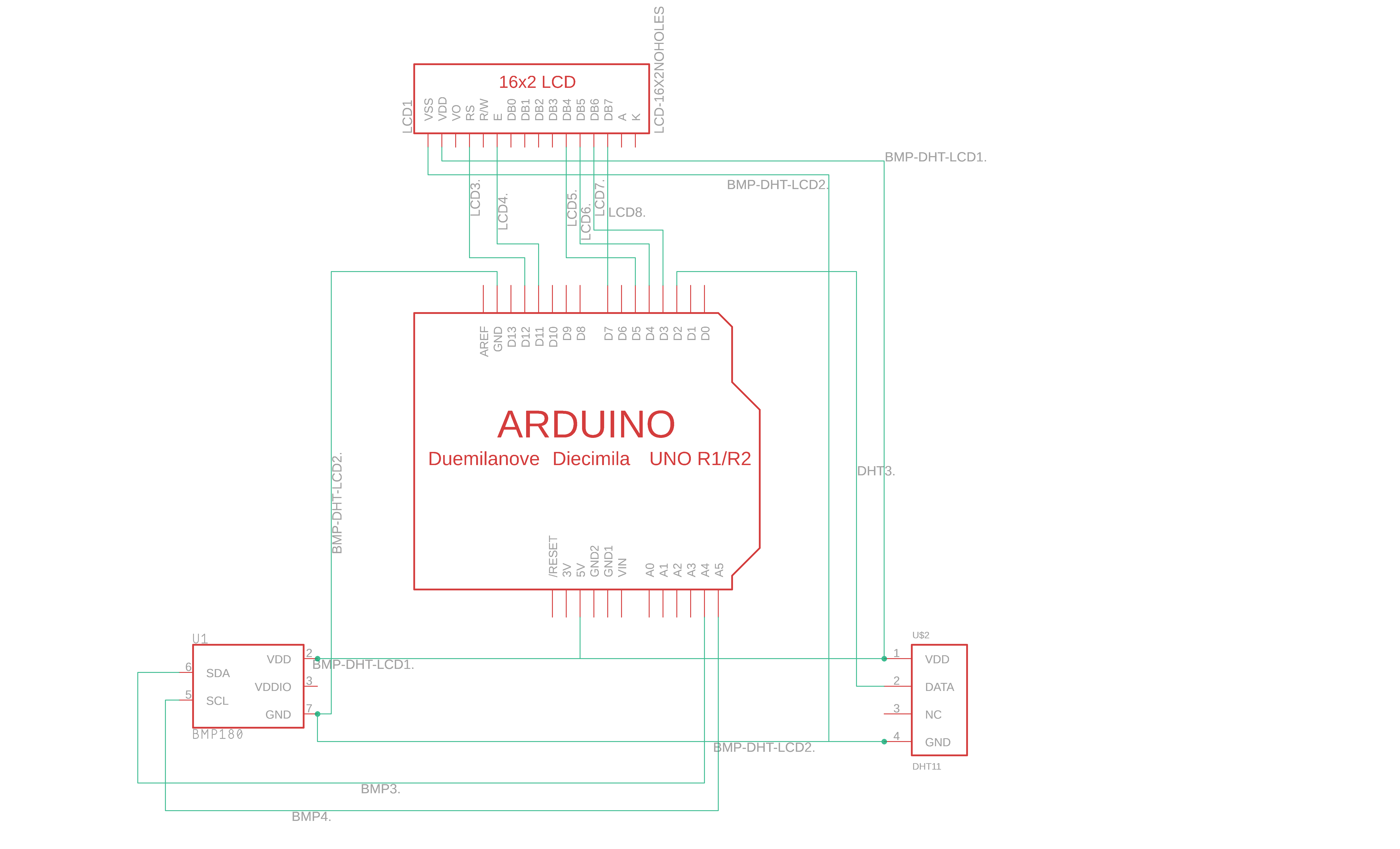
How is everything connected
For the BMP180 sensor
- VCC pin of the BMP180 sensor to the 5V pin on the Arduino Uno;
- GND pin of the BMP180 sensor to one of the GND pins on the Arduino Uno;
- SDA pin of the BMP180 sensor to the SDA (data - pin A4) pin on the Arduino Uno;
- SCL pin of the BMP180 sensor to the SCL (clock - pin A5) pin on the Arduino Uno;
For the DHT11 sensor
- VCC pin of the DHT11 sensor to the VCC pin on the BMP180 sensor;
- GND pin of the DHT11 sensor to the GND pin on the BMP180 sensor;
- DATA pin of the DHT11 sensor to digital pin 2 on the Arduino Uno board;
For the LCD 16x2
- VDD pin on the LCD to the VCC pin on the sensor DHT11;
- VSS pin on the LCD to the GND pin on the sensor DHT11;
- RS pin on the LCD to digital pin 12 on Arduino Uno;
- E pin on the LCD to digital pin 11 on Arduino Uno;
- D4 pin on the LCD to digital pin 5 on Arduino Uno;
- D5 pin on the LCD to digital pin 4 on Arduino Uno;
- D6 pin on the LCD to digital pin 3 on Arduino Uno;
- D7 pin on the LCD to digital Pin 6 on Arduino Uno;
Electric Scheme
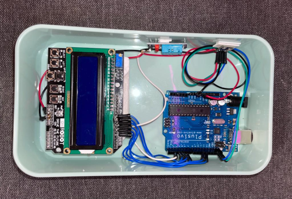
Physical Project
Software Design
How do the sensors work
BMP180
- Sensing Principle: The BMP180 sensor uses a piezo-resistive pressure sensor to measure atmospheric pressure. It contains a microelectromechanical system (MEMS) pressure sensor that changes its resistance based on the applied pressure. The temperature is also measured using an integrated temperature sensor.
- Communication: The BMP180 communicates with an external microcontroller or microprocessor (such as an Arduino) via the I2C (Inter-Integrated Circuit) protocol. It has two communication pins, SDA (Serial Data) and SCL (Serial Clock), which are used for data transfer.
- Initialization: To use the BMP180, the microcontroller sends commands over the I2C interface to initialize the sensor. This includes specifying the measurement mode and configuring the sensor's internal registers.
- Pressure and Temperature Measurement: Once initialized, the BMP180 starts measuring the pressure and temperature. It uses an internal analog-to-digital converter (ADC) to convert the analog pressure and temperature readings into digital values.
- Data Reading: The microcontroller then reads the digital pressure and temperature values from the BMP180 using the I2C interface. The sensor provides the readings in 16-bit format, which can be further processed and converted to meaningful units (e.g., Pascal for pressure, degrees Celsius for temperature) based on the sensor's calibration data.
- Compensation and Calibration: The BMP180 incorporates calibration data stored in its memory, which is used to compensate for sensor-specific variations and temperature effects. These calibration coefficients are used in the calculation formulas to obtain accurate pressure and temperature measurements.
- Data Processing: The microcontroller can perform additional calculations or apply algorithms to the pressure and temperature data as needed. For example, it can convert the pressure reading to altitude or calculate other weather-related parameters.
DHT11
- Sensing Principle: The DHT11 sensor utilizes a capacitive humidity sensor to measure relative humidity (RH). It consists of two electrodes with a moisture-sensitive layer in between. The capacitance of this layer changes with the surrounding humidity, enabling RH measurement. Additionally, a thermistor (resistor that varies with temperature) is used to measure temperature.
- Communication: The DHT11 communicates with an external microcontroller or microprocessor (e.g., Arduino) through a single-wire digital interface. This interface consists of a data line and a power supply line.
- Power Supply: The DHT11 requires a stable power supply of typically 5V. It has three pins: VCC (power supply voltage), GND (ground reference), and a single data pin for bidirectional communication.
- Initialization: To initiate the measurement, the microcontroller sends a start signal to the DHT11 by pulling the data line low for a specific period. After that, the microcontroller releases the data line and waits for the DHT11 to respond.
- Data Transmission: The DHT11 transmits data to the microcontroller in a specific format. It sends a response signal by pulling the data line low for a certain period followed by pulling it high. Then, it transmits the actual data bit by bit. Each bit is represented by the duration the data line remains high after being pulled low.
- Humidity and Temperature Measurement: The DHT11 sequentially sends 8 bits of humidity data, followed by 8 bits of temperature data, and finally an 8-bit checksum to verify the integrity of the data. The microcontroller reads and processes this data to obtain the relative humidity and temperature readings.
- Data Processing: The microcontroller receives the humidity and temperature data from the DHT11 and converts it into meaningful values. The humidity data is typically a percentage value, while the temperature data can be in Celsius or Fahrenheit, depending on the implementation.
Code Part
BMP180
1. Library Initialization:
Including the BMP180 library in the Arduino sketch by adding the library header at the beginning of the code.
#include <Adafruit_Sensor.h>
#include <Adafruit_BMP085.h>
2. Sensor Initialization:
Creating an object for the BMP180 sensor.
Adafruit_BMP085 bmp;
3. Initialization:
In the setup() function of the Arduino sketch, initializing the sensor by calling the begin() function on the BMP180 object and checking if the sensor is working properly.
if (!bmp.begin()) {
lcd.print(“BMP180 error!”);
while (1);
}
4. Reading Sensor Data:
In the loop() function.
float temperature = bmp.readTemperature();
float pressure = bmp.readPressure() / 100.0;
DHT11
1. Library Initialization:
Include the DHT sensor library in the Arduino sketch by adding the library header at the beginning of the code.
#include <DHT.h>
2.Sensor Initialization:
Define the DHT sensor type (DHT11) and the pin to which it is connected.
#define DHTPIN 2
#define DHTTYPE DHT11
DHT dht(DHTPIN, DHTTYPE);
where DHTPIN is the digital pin connected to the data pin of the DHT11, and DHTTYPE is set to DHT11.
3. Initialization:
In the setup() function of your Arduino sketch, initializing the DHT sensor by calling the begin() function on the DHT object.
dht.begin();
4. Reading Sensor Data:
float humidity = dht.readHumidity();
In the loop() function:
LCD
1. Library Initialization: Including the LCD library in the Arduino sketch by adding the library header at the beginning of the code.
#include <LiquidCrystal.h>
2. Object Creation: Creating an LCD object by declaring a variable of the LiquidCrystal class and specifying the pin connections.
LiquidCrystal lcd(12, 11, 5 , 4, 3, 6);
3. Initialization: In the setup() function of the Arduino sketch, initializing the LCD module by calling the begin() function on the LCD object.
lcd.begin(16, 2);, where 16 and 2 are the number of columns and rows of the used LCD module.
4. Displaying Content: In the loop() function:
lcd.clear();
lcd.print(“Temp: ”);
lcd.print(temperature);,
lcd.print() to print text and the data from BMP180 and lcd.clear() to clear the display.
Results

Download
Bibliography and Sources
