
RFID Door Lock
Introduction
The project I want to implement consists of a more secure door / gate locking system. They can be opened using a tag, using the bluetooth application or obviously, using the master card. The purpose of the project is, in short, safety. The whole idea came to me sitting at home realizing that if I have to leave, I should always have the key with me, so why not just have the phone with which I can open any door I want without having 300 keys with me.
General Description
The device uses 2 ways of unlocking the door: RFID Lock and also the phone application. The phone application is unlocking it through a bluetooth module (HC-06) since i want to make it for iOS. The RFID module works using a tag that you can only set with a master card.

Hardware Design
Parts used:
- Arduino NANO - The Arduino Nano is a compact and versatile microcontroller board that is popular among electronics enthusiasts and hobbyists. It is based on the ATmega328P microcontroller and offers a wide range of digital and analog I/O pins, making it suitable for a variety of projects.

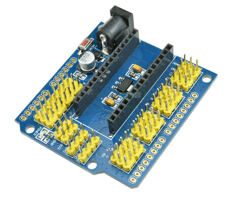
- Expansion Board - An Arduino Nano expansion board is an add-on module designed to extend the capabilities of the Arduino Nano. It provides additional functionality and connectivity options, allowing for easier integration with various sensors, actuators, and other peripherals.
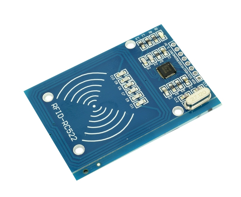
- RFID Module RC522 - The RC522 RFID module is a widely used module that allows for easy integration of RFID (Radio Frequency Identification) capabilities into Arduino projects. It enables reading and writing data on RFID tags, making it ideal for applications such as access control systems, inventory management, and identification purposes.
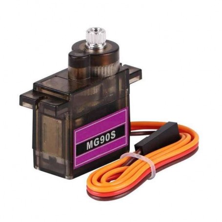
- Servo Motor MG90S - The MG90S servo motor is a popular choice for robotics and hobbyist projects due to its compact size and reliable performance. It offers precise angular control, high torque output, and operates at a wide range of voltages, making it suitable for a variety of applications requiring controlled motion, such as robotic arms, RC vehicles, and automated systems.
- Buzzer - A buzzer is a compact audio device commonly used in electronic projects to generate audible alerts, notifications, or sound effects, allowing for simple integration with microcontrollers like Arduino for implementing various sound-based features.

- Push Buttons - Push buttons are simple mechanical switches commonly used in electronic circuits and Arduino projects to provide a momentary electrical contact when pressed, allowing for user input and control in applications such as menu navigation, mode selection, or triggering specific actions.

- LCD - An I2C LCD (Liquid Crystal Display) module is a convenient and space-saving display solution that uses the I2C communication protocol, allowing for easy integration with Arduino and other microcontrollers to display text, numbers, and even custom characters, making it ideal for providing visual feedback and information in various projects and applications.

Electrical Schematic

Software Design
The software design integrates various libraries and functionalities to create a secure and user-friendly access control solution. It includes the SPI communication library (SPI.h) for RFID communication, the MFRC522 RFID library (MFRC522.h), the Servo library (Servo.h) for controlling the servo motor, the Wire library (Wire.h) for I2C communication, and the LiquidCrystal_I2C library (LiquidCrystal_I2C.h) for the I2C-based LCD display.
The LCD configuration involves creating an instance of the LiquidCrystal_I2C class with the LCD address and dimensions. The LCD backlight is turned on to ensure visibility.
Pin definitions are assigned for various components: RST_PIN for the MFRC522 module reset, SS_PIN as the Slave Select pin for the MFRC522 module, buzzer_pin for the buzzer output, outside_close for the button outside the door to close it, inside_close for the button inside the door to close it, and inside_open for the button inside the door to open it.
Several boolean variables are initialized to track the system state, and an integer variable, timer, is used to hold the timer value. Other variables, such as user_added and add_ID_counter, are used for managing user IDs.
In the setup function, the SPI bus is initialized, the MFRC522 module is initialized, the servo motor is attached to the PWM signal, the buzzer pin is configured as OUTPUT, and the button pins are configured as INPUT. The LCD display is also initialized, and initial messages are printed on it.
The areArraysEmpty function checks if the user ID arrays are empty, indicating whether any user IDs have been added.
In the loop function, the system checks if the buttons outside or inside the door are pressed to close the door. When normal_mode is true, it handles the countdown, cancels the new ID addition process if necessary, and grants or denies access based on the presented RFID card. When normal_mode is false, it displays instructions for placing a new ID card, initiates a countdown, and cancels the new ID addition process if a card is presented during the countdown.
Overall, the software design combines RFID communication, servo motor control, user interface management, and audio feedback to create a secure and user-friendly access control system. It incorporates error handling, code modularity, and configuration/customization options to enhance functionality, maintainability, and adaptability.
Download
Journal
- Basically the project is done, I only have to slightly improve the code and it is done. Down below I have uploaded some pictures with the project itself for which I have also done a box using a 3D printer.


