
This is an old revision of the document!
Lab 9 - IPSec and GRE
Topology
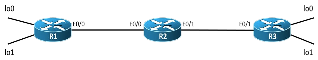
Interfaces
| Device | Interface | IP Address | Subnet Mask |
|---|---|---|---|
| R1 | Fa0/0 | 192.168.12.1 | 255.255.255.248 |
| R1 | Lo0 | 10.1.1.1 | 255.255.255.0 |
| R1 | Lo1 | 11.1.1.1 | 255.255.255.0 |
| R2 | Fa0/0 | 192.168.12.2 | 255.255.255.248 |
| R2 | Fa0/1 | 192.168.23.2 | 255.255.255.248 |
| R3 | Fa0/0 | 192.168.23.3 | 255.255.255.248 |
| R3 | Lo0 | 10.3.3.3 | 255.255.255.0 |
| R3 | Lo1 | 11.3.3.3 | 255.255.255.0 |
Tasks
Open the Lab9_CNS_Topology.net file.
- [2p] Configure the above topology with the IP addresses shown in the IP Addressing table. Configure EIGRP/OSPF in the above topology in order to have end-to-end connectivity.
- Do an extended from R1’s lo1 interface to R3’s lo1 interface.
- [+5p=7p] Configure so that traffic between R1 Lo0 and R3 Lo0 is encrypted using IPSec.
- Configure the following ISAKMP policy on both R1 and R3
- authentication: pre-shared keys
- encryption: aes 256
- hashing: sha1
- diffie-hellman group: 2
- lifetime: 3600
- Configure “srs!@#” as a pre-shared key on both R1 and R3.
- Configure the following transform set on both R1 and R3:
- Tag (name of the transform set): TS_SRS
- Transform set: esp-aes 256 esp-sha-hmac
- Mode: transport
- Construct an access-list that will match the traffic that you want to encrypt. The access-list will have to define both the source and the destination of the traffic. An access-list must be defined on both R1 and R3. Watch out for the fact that the 2 ACLs must mirror each other.
- Create a crypto-map called TUNNEL_MAP on both R1 and R3.
- The crypto map must match the ACL that you used to define interesting traffic.
- The crypto map must set the remote peer for the tunnel. The remote peer is going to be the IP address of the outgoing Ethernet interface of each router.
- The crypto map must set the transform set to “TS_SRS”
- Apply the crypto map on interface F0/0 of R1 and F0/1 of R3.
- Verifying that the traffic is encrypted.
- Use the “capture R2 F0/0 tunnel.cap” command in the dynagen console to start a capture on R2’s F0/0 interface
- Generate traffic between loopback interfaces.
- Stop the capture using the “no capture R2 F0/0” command in the dynagen console.
- Open the tunnel.cap file with Wireshark.
- [+4p=11p] All the traffic that will be flowing between R1’s lo1 interface and R3’s lo1 interface is to be encapsulated using the GRE protocol.
- The network that is to be used on the Tunnel interfaces is 13.13.13.0 /29
- The tunnel mode is “gre ip”
- On R1, direct all the traffic going to network 11.3.3.0 through the GRE tunnel. Depending on what routing protocol you use, watch out for:
- routes being advertised through the tunnel (including the route towards the tunnel endpoint)
- the subnet mask of dynamic/static routes
- On R3, direct all the traffic going to network 11.1.1.0 through the GRE tunnel.
- Verifying the GRE encapsulation using Wireshark.
