
This is an old revision of the document!
RP2040 internals: PWM, ADC and PIO
PWM
In embedded applications, keeping track of time is crucial. Even for the simple task of blinking a led at a certain time interval, we need a reference of time that is constant and precise.
A clock is a piece of hardware that provides us with that reference. Its purpose is to oscillate at a fixed frequency and provide a signal that switches from high to low at a fixed interval.
The most precise type of clock is the crystal oscillator (XOSC). The reason why it is so accurate is because it uses the crystal's natural vibration frequency to create the clock signal. This clock is usually external to the processor itself, but the processor also has an internal clock (ROSC) that is less accurate and that can be used in cases where small variations of clock pulses are negligible. When using the USB protocol, for instance, a more stable clock signal is required, therefore the XOSC is necessary. The crystal oscillator on the Raspberry Pi Pico board has a frequency of 12MHz.
This clock signal is just a reference, and most of the time we need to adjust it to our needs. This is done by either multiplying or dividing the clock, or in other words, elevating or lowering the frequency of the clock. For example, the RP2040 itself runs on a 125MHz clock, so the crystal oscillator frequency of 12MHz is multiplied (this is done using a method called Phase-Locked Loop).
A counter is a piece of hardware logic that counts, as its name suggests. Every clock cycle, it increments the value of a register, until it overflows and starts anew.

The way the counter works here is that it increments/decrements every clock cycle and checks whether or not it has reached its reset value. If is has, then it resets to its initial value and starts all over again.
The ARM Cortex-M uses the SysTick time counter to keep track of time. This counter is decremented every microsecond, and when it reaches 0, it triggers an exception and then resets.
- SYST_CVR register - the value of the timer itself
- SYST_RVR register - the reset value
- SYST_CSR_SET register:
- ENABLE field - enable/disable the counter
- TICKINT field - enable/disable exception on reaching 0
An alarm is a counter that triggers an interrupt every time it reaches a certain value. This way, an alarm can be set to trigger after a specific interval of time, and while it's waiting, the main program can continue executing instructions, and so it is not blocked. When the alarm reaches the chosen value, it goes off and triggers an interrupt that can then be handled in its specific ISR.
Up to now, we learned to turn a led on and off, or in other words, set a led's intensity to 100% or 0%. What if we wanted to turn on the led only at 50% intensity? We only have a two-level digital value, 0 or 1, so technically a value of 0.5 is not possible. What we can do is simulate this analog signal, so that it looks like the led is at half intensity.
Pulse-Width Modulation (PWM) is a method of simulating an analog signal using a digital one, by varying the width of the generated square wave.
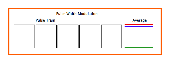 |  |
The duty cycle of the signal is the percentage of time per period that the signal is high.
$D[\%] = \frac{t\_on}{t\_on + t\_off} \cdot 100 = \frac{pulse\_width}{period} \cdot 100$
Thus, the average voltage reaching the device is given by the relationship: D * Vcc.So if we wanted our led to be at 50% intensity, we would choose a duty cycle of 50%. By quickly switching between high and low, the led appears to the human eye as being at only 50% intensity, when in reality, it's only on at max intensity 50% of the time, and off the rest of the time.
For the RP2040, to generate this PWM signal, a counter is used. The PWM counter is controlled by these registers (X can be from 0-7, depending on the channel):
- CHX_CTR - the actual value of the counter
- CHX_CC - the value that the counter will compare to
- CHX_TOP - the value at which the counter will reset (or wrap)
When CHX_CTR is reset, the value of the output signal is 1. The counter counts up until it reaches CHX_CC, after which the value of the output signal becomes 0. The counter continues to count until it reaches CHX_TOP, and then the signal becomes 1 again. This way, by choosing the value of CHX_CC, we set the duty cycle of the PWM signal.
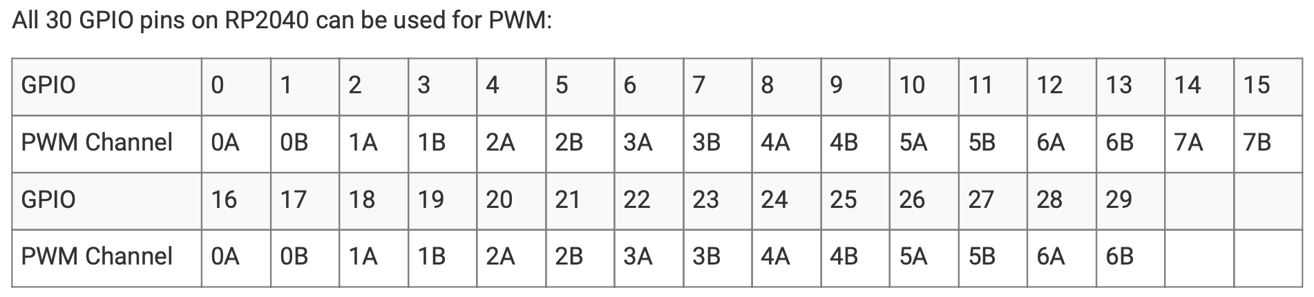
On RP2040, all GPIO pins support PWM. Every two pins share a PWM slice, and each one of them is on a separate channel.
Here's how to initialize and use PWM on a pin in RP2040 using Pico SDK:
- Include Libraries:
#include <hardware/pwm.h>
- Set up GPIO pin, slice and PWM slice:
    const uint count_top = 1000;
    float output_duty_cycle = 0.2f;
    uint slice = pwm_gpio_to_slice_num(gpio);

    pwm_config cfg = pwm_get_default_config();
    pwm_config_set_wrap(&cfg, count_top);
    pwm_init(slice, &cfg, true);

    gpio_set_function(gpio, GPIO_FUNC_PWM);
- Set PWM Duty Cycle:
pwm_set_gpio_level(gpio, (uint16_t) (output_duty_cycle * (count_top + 1)));
- Enable PWM Output (Optional):+
pwm_set_enabled(slice, true);
ADC
Now we know how to represent an analog signal using digital signals. There are plenty of cases in which we need to know how to transform an analog signal into a digital one, for example a temperature reading, or the voice of a person. This means that we need to correctly represent a continuous wave of infinite values to a discrete wave of a finite set of values. For this, we need to sample the analog signal periodically, in other words to measure the analog signal at a fixed interval of time. This is done by using an Analog-to-Digital converter.
The ADC has two important parameters that define the quality of the signal representation:
- Sampling rate - frequency at which a new sample is read: The higher the sampling rate, the more samples we get, so the more accurate the representation of the signal
- Resolution - number of bits which we can use in order to store the value of the sample: The higher the resolution, the more values we can store, so the more accurate the representation
The Nyquist-Shannon sampling theorem serves as a bridge between continuous-time signals and discrete-time signals. It establishes a link between the frequency range of a signal and the sample rate required to avoid a type of distortion called aliasing. Aliasing occurs when a signal is not sampled fast enough to construct an accurate waveform representation.
For an analog signal to be represented without loss of information, the analog signal needs to be sampled at a frequency greater than twice the maximum frequency of the signal. In other words, we must sample at least twice per cycle.
A photoresistor (or photocell) is a sensor that measures the intensity of light around it. Its internal resistance varies depending on the light hitting its surface; therefore, the more light there is, the lower the resistance will be.
PIO
Exercises
- Prepare your setup for Marble Pico interaction with VS Code and pico SDK or use Arduino IDE support according to instructions available here: Ardushop Marble Pico.
References
