
RP2040 internals: PWM, ADC and PIO
PWM
In embedded applications, keeping track of time is crucial. Even for the simple task of blinking a led at a certain time interval, we need a reference of time that is constant and precise.
A clock is a piece of hardware that provides us with that reference. Its purpose is to oscillate at a fixed frequency and provide a signal that switches from high to low at a fixed interval.
The most precise type of clock is the crystal oscillator (XOSC). The reason why it is so accurate is because it uses the crystal's natural vibration frequency to create the clock signal. This clock is usually external to the processor itself, but the processor also has an internal clock (ROSC) that is less accurate and that can be used in cases where small variations of clock pulses are negligible. When using the USB protocol, for instance, a more stable clock signal is required, therefore the XOSC is necessary. The crystal oscillator on the Raspberry Pi Pico board has a frequency of 12MHz.
This clock signal is just a reference, and most of the time we need to adjust it to our needs. This is done by either multiplying or dividing the clock, or in other words, elevating or lowering the frequency of the clock. For example, the RP2040 itself runs on a 125MHz clock, so the crystal oscillator frequency of 12MHz is multiplied (this is done using a method called Phase-Locked Loop).
A counter is a piece of hardware logic that counts, as its name suggests. Every clock cycle, it increments the value of a register, until it overflows and starts anew.

The way the counter works here is that it increments/decrements every clock cycle and checks whether or not it has reached its reset value. If is has, then it resets to its initial value and starts all over again.
The ARM Cortex-M uses the SysTick time counter to keep track of time. This counter is decremented every microsecond, and when it reaches 0, it triggers an exception and then resets.
- SYST_CVR register - the value of the timer itself
- SYST_RVR register - the reset value
- SYST_CSR_SET register:
- ENABLE field - enable/disable the counter
- TICKINT field - enable/disable exception on reaching 0
An alarm is a counter that triggers an interrupt every time it reaches a certain value. This way, an alarm can be set to trigger after a specific interval of time, and while it's waiting, the main program can continue executing instructions, and so it is not blocked. When the alarm reaches the chosen value, it goes off and triggers an interrupt that can then be handled in its specific ISR.
Up to now, we learned to turn a led on and off, or in other words, set a led's intensity to 100% or 0%. What if we wanted to turn on the led only at 50% intensity? We only have a two-level digital value, 0 or 1, so technically a value of 0.5 is not possible. What we can do is simulate this analog signal, so that it looks like the led is at half intensity.
Pulse-Width Modulation (PWM) is a method of simulating an analog signal using a digital one, by varying the width of the generated square wave.
 |  |
The duty cycle of the signal is the percentage of time per period that the signal is high.
$D[\%] = \frac{t\_on}{t\_on + t\_off} \cdot 100 = \frac{pulse\_width}{period} \cdot 100$
Thus, the average voltage reaching the device is given by the relationship: D * Vcc.So if we wanted our led to be at 50% intensity, we would choose a duty cycle of 50%. By quickly switching between high and low, the led appears to the human eye as being at only 50% intensity, when in reality, it's only on at max intensity 50% of the time, and off the rest of the time.
For the RP2040, to generate this PWM signal, a counter is used. The PWM counter is controlled by these registers (X can be from 0-7, depending on the channel):
- CHX_CTR - the actual value of the counter
- CHX_CC - the value that the counter will compare to
- CHX_TOP - the value at which the counter will reset (or wrap)
When CHX_CTR is reset, the value of the output signal is 1. The counter counts up until it reaches CHX_CC, after which the value of the output signal becomes 0. The counter continues to count until it reaches CHX_TOP, and then the signal becomes 1 again. This way, by choosing the value of CHX_CC, we set the duty cycle of the PWM signal.
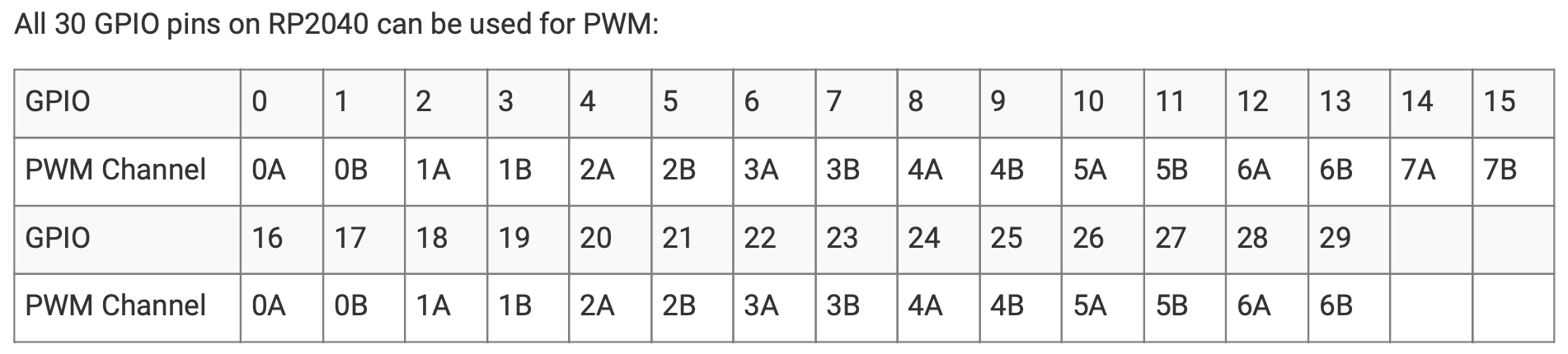
On RP2040, all GPIO pins support PWM. Every two pins share a PWM slice, and each one of them is on a separate channel.
Here's how to initialize and use PWM on a pin in RP2040 using Pico SDK:
- Include Libraries:
#include <hardware/pwm.h>
- Set up GPIO pin, slice and PWM slice:
    const uint count_top = 1000;
    float output_duty_cycle = 0.2f;
    uint slice = pwm_gpio_to_slice_num(gpio);

    pwm_config cfg = pwm_get_default_config();
    pwm_config_set_wrap(&cfg, count_top);
    pwm_init(slice, &cfg, true);

    gpio_set_function(gpio, GPIO_FUNC_PWM);
- Set PWM Duty Cycle:
pwm_set_gpio_level(gpio, (uint16_t) (output_duty_cycle * (count_top + 1)));
- Enable PWM Output (Optional):+
pwm_set_enabled(slice, true);
ADC
Now we know how to represent an analog signal using digital signals. There are plenty of cases in which we need to know how to transform an analog signal into a digital one, for example a temperature reading, or the voice of a person. This means that we need to correctly represent a continuous wave of infinite values to a discrete wave of a finite set of values. For this, we need to sample the analog signal periodically, in other words to measure the analog signal at a fixed interval of time. This is done by using an Analog-to-Digital converter.
The ADC has two important parameters that define the quality of the signal representation:
- Sampling rate - frequency at which a new sample is read: The higher the sampling rate, the more samples we get, so the more accurate the representation of the signal
- Resolution - number of bits which we can use in order to store the value of the sample: The higher the resolution, the more values we can store, so the more accurate the representation
The Nyquist-Shannon sampling theorem serves as a bridge between continuous-time signals and discrete-time signals. It establishes a link between the frequency range of a signal and the sample rate required to avoid a type of distortion called aliasing. Aliasing occurs when a signal is not sampled fast enough to construct an accurate waveform representation.
For an analog signal to be represented without loss of information, the analog signal needs to be sampled at a frequency greater than twice the maximum frequency of the signal. In other words, we must sample at least twice per cycle.
A photoresistor (or photocell) is a sensor that measures the intensity of light around it. Its internal resistance varies depending on the light hitting its surface; therefore, the more light there is, the lower the resistance will be.
The RP2040 microcontroller integrates a 12-bit ADC for converting analog voltage signals from external sensors or circuits into digital values usable by your program, meaning it can represent analog voltages with 4096 (2^12) discrete values. Each input channel can measure voltages between 0V (ground) and the ADC reference voltage (typically the RP2040's internal 3.3V supply, but you can use an external reference for higher accuracy).
By configuring the input mux, you can select the desired channel (external sensor or internal temperature) for conversion. The ADC offers a multiplexer (mux) that allows selecting one of five available input channels:
- Four External Inputs are shared with GPIO pins 26 to 29. You can connect external sensors (e.g., photoresistors, voltage dividers) to these pins for measurement.
- One internal dedicated Temperature Sensor accessible through the ADC. This allows you to monitor the chip's temperature within your program.
In order to setup the ADC you need to follow the next steps:
- Include the libraries:
#include <hardware/adc.h>
- Configure the ADC pin:
    adc_init();

    // Make sure GPIO is high-impedance, no pullups etc
    adc_gpio_init(26);
    // Select ADC input 0 (GPIO26)
    adc_select_input(0);
- Read the ADC values:
    // 12-bit conversion, assume max value == ADC_VREF == 3.3 V
    const float conversion_factor = 3.3f / (1 << 12);
    uint16_t result = adc_read();
For the internal temperature sensor able to read the MCU temperature you can have a look over the following example: onboard_temperature
PIO
The RP2040 goes beyond traditional microcontrollers by offering two Programmable I/O (PIO) blocks. These PIOs are essentially mini-state machines that can execute custom instructions, allowing you to precisely control hardware interactions without relying solely on the main CPU.
Some of the benefits for PIOs include:
- Offload Work: PIOs free up the main CPU for other tasks while handling repetitive or time-critical operations related to hardware interaction.
- Fine-grained Control: PIO instructions offer precise control over GPIO pins, enabling features like custom bit manipulation, pulse generation, and protocol implementation.
- Efficiency: PIOs operate independently with dedicated hardware, resulting in potentially lower power consumption compared to CPU-driven I/O.
PIO is programmable in the same sense as a processor. There are two PIO blocks with four state machines each, that can independently execute sequential programs to manipulate GPIOs and transfer data. Unlike a general purpose processor, PIO state machines are highly specialized for IO, with a focus on determinism, precise timing, and close integration with fixed-function hardware. Each state machine is equipped with:
- Two 32-bit shift registers – either direction, any shift count
- Two 32-bit scratch registers
- 4×32-bit bus FIFO in each direction (TX/RX), reconfigurable as 8×32 in a single direction
- Fractional clock divider (16 integer, 8 fractional bits)
- Flexible GPIO mapping
- DMA interface, sustained throughput up to 1 word per clock from system DMA
- IRQ flag set/clear/status
It can be used for multiple purposes such as: generate a precise square wave at a specific frequency on a GPIO pin, ideal for driving LEDs or communication protocols, manipulating data bits in and out of GPIO pins, a PIO can emulate a shift register for interfacing with serial devices or handle complex communication protocols like SPI (Serial Peripheral Interface) or I2C (Inter-Integrated Circuit) by generating the necessary control signals for data transfer.
The four state machines execute from a shared instruction memory. System software loads programs into this memory, configures the state machines and IO mapping, and then sets the state machines running. PIO programs come from various sources: assembled directly by the user, drawn from the PIO library, or generated programmatically by user software.
From this point on, state machines are generally autonomous, and system software interacts through DMA, interrupts and control registers, as with other peripherals on RP2040. For more complex interfaces, PIO provides a small but flexible set of primitives which allow system software to be more hands-on with state machine control flow.
PIO state machines execute short, binary programs. Programs for common interfaces, such as UART, SPI, or I2C, are available in the PIO library, so in many cases, it is not necessary to write PIO programs. However, the PIO is much more flexible when programmed directly, supporting a wide variety of interfaces which may not have been foreseen by its designers.
The PIO has a total of nine instructions: JMP, WAIT, IN, OUT, PUSH, PULL, MOV, IRQ, and SET. Though the PIO only has a total of nine instructions, it would be difficult to edit PIO program binaries by hand. The PIO assembler is included with the SDK, and is called pioasm. This program processes a PIO assembly input text file, which may contain multiple programs, and writes out the assembled programs ready for use. For the SDK these assembled programs are emitted in form of C headers, containing constant arrays.
The following directives control the assembly of PIO programs:
- .define ( PUBLIC ) <symbol> <value>: Define an integer symbol named <symbol> with the value <value>. If this .define appears before the first program in the input file, then the define is global to all programs, otherwise it is local to the program in which it occurs. If PUBLIC is specified the symbol will be emitted into the assembled output for use by user code.
- .program <name>: Start a new program with the name <name>. Note that that name is used in code so should be alphanumeric/underscore not starting with a digit. The program lasts until another .program directive or the end of the source file. PIO instructions are only allowed within a program
- .origin <offset>: Optional directive to specify the PIO instruction memory offset at which the program must load. Most commonly this is used for programs that must load at offset 0, because they use data based JMPs with the (absolute) jmp target being stored in only a few bits.
- .side_set <count> (opt) (pindirs): If this directive is present, <count> indicates the number of side-set bits to be used. Additionally opt may be specified to indicate that a side <value> is optional for instructions (note this requires stealing an extra bit — in addition to the <count> bits — from those available for the instruction delay). Finally, pindirs may be specified to indicate that the side set values should be applied to the PINDIRs and not the PINs.
- .wrap_target: Place prior to an instruction, this directive specifies the instruction where execution continues due to program wrapping.
- .wrap: Placed after an instruction, this directive specifies the instruction after which, in normal control flow (i.e. jmp with false condition, or no jmp), the program wraps (to .wrap_target instruction).
- .lang_opt <lang> <name> <option>: Specifies an option for the program related to a particular language generator.
- .word <value>: Stores a raw 16-bit value as an instruction in the program.
For more information on values, expressions, labels and instructions supported by PIO please consult the datasheet at chapter 3.3. For example on how to use PIO consult the pico pio examples.
Exercises
- Prepare your setup for Marble Pico interaction with VS Code and pico SDK or use Arduino IDE support according to instructions available here: Ardushop Marble Pico.
References
