

Lab 4: Programming with Streams
Traffic Lights
What you need
- One Raspberry Pi connected to Wyliodrin STUDIO;
- Five LEDs;
- One button;
- Six 200 Ohms resistors;
- Jumper wires;
- Breadboard.
The Setup
Connect the LEDs and the button to the Raspberry Pi following the schematics in the figure.
 The button is connected in a voltage divider circuit. You can notice that the button has 4 legs. Usually, one leg from one side is connected to the one in front of it. However, there might be the case that the legs care connected side by side, this is why we encourage you to use a measuring device in order to identify how the legs are connected. Once the button is pressed, all the legs get connected.

In the schematics, the button is connected to a pull-up resistor, that means that the GPIO pin will read the value 1 if the button is pressed and 0 otherwise.
The Code
Create a new Wyliodrin STUDIO application and name it traffic lights.

The previous shows the nodes you need to use and how to connect them. Now let's see what each node does.
First of all, notice the semaphore function node. This node is connected to the nodes controlling the GPIO pins connected to the LEDs and it outputs the values that need to be written on each pin.
The figure below shows the code of the function. Basically, it verifies the value of the payload it received and depending on the value, it describes a certain state. The value 0 corresponds to the initial state when the cars lights have their green light turned on and the rest turned off and the pedestrian lights have the red light turned on and the green one turned off. This is why the function returns a list containing the values [0,0,1,1,0]. The block automatically knows to distribute each of these values in a message on the corresponding output (the first value is transmitted on the first output, the second value on the second output and so on). As a result, the digital write nodes (red, yellow, green, ped-red and ped-greed) receive the values 0,0,1,1 and respectively 0.

The digital write nodes have names according to the LED they control (the red node controls the red LED of the cars' semaphore and so on). Each node controls a pin by either setting it to HIGH or to LOW. The pin will be set to HIGH if the payload of the message is 1 and to LOW if it equals 0. For each node, you need to select the number of the pin they are controlling. For the red node you need to type the number 2 for the pin, as the LED representing the red light is connected to GPIO 2.
Another important aspect are the two run nodes. The one directly connected to the set 0 node will get triggered once the application start running and then it will send a message every 48 hours. For this, you need to double click the node and mark the Fire once at start?. Afterwards, you also need to set the interval to every 48 hours.
The node connected to run. set 0 is a change node and it allows you to change the payload of the message. As the first state of the system is 0, the payload is set to 0 and sent to the function. Basically, the run-set 0- function connection resets the traffic lights every 48 hours. All the other set nodes work the same, but they set some other values to the payload.

The other run node is connected to digital read, so each second a new reading is done.
The digital read node reads the value coming from the button. You have to set the number of the pin the reading should be done from. In this case, the button is connected to pin 6, so go to the node's properties and set 6 for the pin.
If the value read is 1 (HIGH), you need to change the states of the lights, otherwise you can simply ignore the reading. The node named if button pressed is a switch node that routes messages based on their properties. This specific node has only one output which will send further on any message that has the payload 1, basically it will act as a filter which sends a message only when the button is pressed. The figure below depicts how to filter the values.

The switch node is then connected to a trigger node. This node creates two messages whenever a message arrives on the input and it outputs the messages separated by a distance specified in the properties. For this project the node allows you to automatically send a message after 30 seconds from the pushed button so that the traffic lights system returns to its initial state. The first message has the payload 1 and the second has the payload 0, thus identifying the states the lights need to get to.

Further on, depending on the value the trigger node outputs, the filter input node will set the lights to the intermediate state and after 5 seconds (delay node) it will send another message with the value of final state stored in the payload.
The filter input node is also a switch node which has two outputs, in this case. The first output is for the value 0 (triggered when the button has just been presses) and the second for the value 1 (triggered when the system needs to get back to its initial state). This way you can differentiate between the two.

Exercises
- Use a button in the dashboard to control the traffic lights;
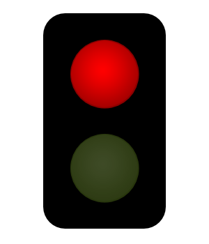
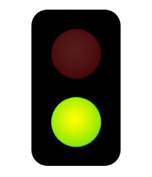
- Display in the dashboard the state of the traffic lights using the extra widget. Note: you can use the following pictures:
- pedestrians red light on: https://dl.dropbox.com/s/sjr52ohr8pxb9he/pedestrian-lights-red.png?dl=0
- pedestrians green light on: https://dl.dropbox.com/s/m1ritf34ethvgt2/pedestrian-lights-green.png?dl=0
