Lecture 3: Software for the Internet of Things
This particular course will make a sum up of the software used in the IoT field and describe in detail such programming languages as Streams or Visual programming. In addition, it will introduce the student into signal processing.
Software for IoT - Wyliodrin
Wyliodrin is an online platform for programming different IoT projects while all the created applications are stored in the Cloud. In case you want to build simple or complicated applications on embedded boards, Wyliodrin is a programming solution with a large palette of languages and functions. There are many features of Wyliodrin that make programming way easier and enjoyable. You need a board that runs Linux and has an Internet connection in order to be able to use it with this service. As the embedded boards, such as the Intel Edison, that are supported by Wyliodrin are basically computers, you can run several projects at the same time on a single board as long as they do not interfere with each other. It is important that the projects do not write on the same GPIOs.
Some of Wyliodrin's features are the following:
* Dashboard: you can add charts to your projects. These have a debugging function. You can watch the progress of your application, the graphic representation of the values sent by the sensors and check for mistakes. However, it is not designed for long time usage or for deploying software.
To use it, you simply click on the chart you prefer and drag and drop it around the dashboard. Another great feature is the fact that you can export the values from the chart to plot them in other types of software.
* Wyliodrin has an open source library, which means that the projects can be used even if you decide not to use Wyliodrin anymore. Initially Wyliodrin started from the Arduino library, which was cloned and later adapted to suit embedded boards. The specifications are those of the Arduino library, but Wyliodrin adapted the API for each type of board supported on the platform.
* The languages that you can use in Wyliodrin to build a project are varied. If you want to code, you can start doing it in either C, C++, JavaScript, Python and others, but also you can decide to use Visual programming or Streams. A very important aspect is that it is completely hardware independent, so ,if you decide to change the board at some time, you will be able to run the same code on it, with very small changes like the pin numbering, because each board has different pins, but the API should be the same.
The functions most used from the Arduino-like library, libwyliodrin, are:
- pinMode will give to the pin the characteristic of input or output
- digitalWrite and analogWrite do exactly what's expected: they write values on digital or PWM pins.
- digitalRead and analogRead will consequently read values from digital or analog pins. For the latter, you can have 10 bit, 12 bit or other ADCs, thus the values received are scaled so they stay between 0 and 1024.
Languages
As mentioned before,there are many languages available to program a project.
C is mostly important for micro controllers. For small, simple projects (prototyping) Visual programming is the best option. On the other hand, for more complex applications writing code is more practical. Visual can still help, by generating the Python and Java Script code you will simply copy paste in your project.
Visual Programming
Visual Programming is adapted for hardware, having as starting point Google Blockly. You also can use this for documentation, drag some blocks and see the code for them in Python or JavaScript, that will help you if you do not know how some function work or what parameters they use.
Streams Programming
Streams programming language is inspired from node-RED developed by IBM. This language is a data driven one, as opposed to imperative programming languages. It is based on events, so an action occurs at the moment when data arrives in a certain point.
Streams language works by sending messages from one node to the other. This message will be stored in the payload, which is a necessary property of a node. Another property is the topic. It contains information about the payload, but it is optional. A node has only one input, but possibly multiple outputs.
Apart from nodes, another type of components are the data routes. They are routing rules for sending data among nodes.
After a Streams program is built and run, it is converted to imperative language, as this is the only way a computer can understand and execute it. The code can't be shown for the nodes, as it is for Visual blocks, because it is way more complicated, making possible the conversion.
Most of the nodes are:
Run node, Function and Digital Write
Run node is the block which will start the payload. This is practically the first data flow sent towards the rest of the nodes you use in an application. In its settings you have three fields. If no payload is specified the payload is set to the current time in milliseconds since 1970. This allows subsequent functions to perform time based actions. You can write it yourself if you chose for it to be a string. The topic field can hold data to be used later, in other functions. The repeat option does what it says and continuously sends the payload every x seconds.The Fire once at start option actually waits 50mS before firing to give other nodes a chance to instantiate properly.
The function node is a block where you can write code to do many other interesting things. By convention, it will have a “msg.payload” property containing the body of the message. If you double click on it, you will find the name field, the second field, where you write the code and the last one, where you specify how many outputs the node has.
Digital Write node will write 0 or 1 on a digital pin, the one that you choose in the settings. Digital Read is the node that reads the digital value on the corresponding pin. You specify this pin in its settings.
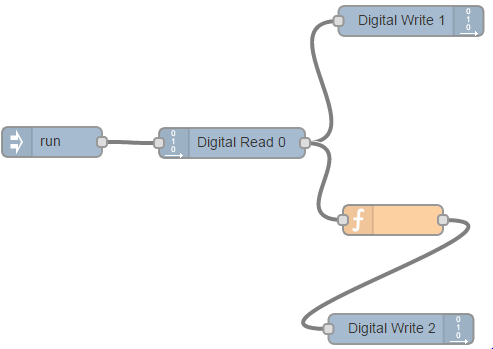
In the example above, two LEDs will take turns at being alight while the other one is off, at the press of one button. More specifically, when you press the button one LED is on, the other off, whereas when the button is not pressed, the LEDs behave in the opposite manner.
Theoretically, the run node sends a message every one second, thus the value from the digital pin is read once a second. The direct value will go to one LED, the one on in 1. The function block will reverse this value and send it to pin 2.
AnalogWrite
Analog Write node writes a value to an analog/PWN pin. It works similarly to Digital Write in terms of what you can do: specify the pin and the value in its configuration or use the message object to set it up. Pay attention that although you can write a signal with the root mean square of, for example 2.5 V, the pick value is still 5V. So if you need to power a device at a voltage of 2.5 V DC (!) you might damage it.
In this example use the PWM pins to light up an LED gradually. As you might remember from the previous course, the PWM pins generate signals with variable duty cycle. In the case of Intel Edison you can control the duty by writing a number between 0 and 255 on the pin. Where 0 corresponds to 0% duty and 255 to 100%. The effect will be that the LED will turn on and off so fast that your eyes will see it as if the LED is not fully on.
You use the run node again with the times option at an interval of 0.1 seconds. In the function you compute the modulo 256 of the counter generating this way sequences of numbers from 0 to 255. It will look as is the LED gradually lights, then goes off and so on.
Print and Analog Read
Analog Read node reads the value from the analog pin mentioned in the settings.
The print node can be connected to the output of any node. It will display msg.payload field of any messages it receives.
In the example, you connect a light sensor on analog input pin A0, read its value, that is stored in msg.payload property, then print it in the console.
Switch and Trigger
Switch node is a function which will evaluate the message received and pass it on after filtering it through a set of rules. You can create the rules in the node's settings.
The trigger is the node which will send a value as soon as it receives a message, It will then wait for a certain amount of time and send another message. The trigger can be extended to send the first value as long as it gets a message and the next value when the message stops.
In this example you connect a button to GPIO pin number 2, pass its value to a switch that only forwards the message when it has a value of 1 (button is pressed). This will make the trigger send a message with payload 1 to the following node, Digital Write, wait for 3 seconds then send another message with payload 0. Having in mind the previous examples, can you guess what the effect is? When the button is pressed the LED will light up for 3 seconds.
Buffer and Send Signal
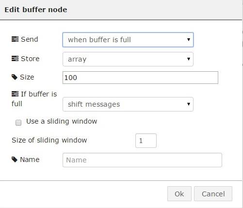
The buffer node is similar to a value node, the difference here is that what a buffer stores is an array. It works like this: every time a new message comes, it will be saved in the array. From the moment the array is full, there are more proceeding methods. One, the array will be sent forward in the payload. Another, it will erase the first element and add a new one or it will store the array , drop whichever message comes, while waiting for a certain event to send out the array.
Send Signal sends the value of the payload to the signal with the same name in the dashboard or to a certain number of boards.
In this example you collect data from a sensor, using Analog Read, store it in an array of 100 elements and send it to a plot on the dashboard.


