Table of Contents
Smart Trash Bin
ȘTEFĂNOIU Ioana-Cristina
Introduction
Smart Trash Bin is an Arduino project that offers users a more hygienic way of disposing of waste, avoiding direct contact with the lid.
Video for the final version of the project: final.ogg
The LED indicators that show the level of fill of the bin can help optimize waste collection and disposal efficiently, preventing overfilling and reducing maintenance time and costs. The automatic lid-opening function can also save energy by opening only when necessary, avoiding accidental or unwanted opening. The automatic opening feature makes the trash bin more comfortable and easier to use for people with reduced mobility or health problems, as well as for the elderly and children.


General Description
My project consists of creating a trash bin equipped with an ultrasonic sensor that detects hand motion and triggers the opening of the lid. The lid opening mechanism will use a motor.
Inside the trash bin, I will install three sets of infrared LED transmitter and receiver, which will identify the degree of filling of the bin. The information will be displayed through a LCD display, that will show the percentage of trash bin fill level.
Upon departure of the user, from the immediate vicinity of the bin, the speaker will emit a sound of gratitude for use.


Hardware Design
The components used are as follows:
| Components | Pictures |
|---|---|
| 1. SENZOR ULTRASONIC HC-SR04 | hc-sr04.png |
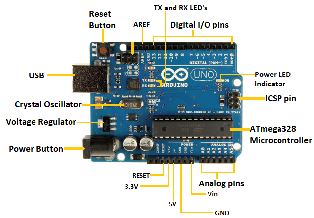
| 2. Arduino UNO | arduino-uno2.png |
| 3. ELECTROMAGNET ELECTRIC 3KG DC12V | electromagnet.jpg |
| 4. 0.5W, 8Ohm SPEAKER | speaker.png |
| 5. LED 5MM IR RECEIVER | ir.png |
| 6. LED 5MM IR TRANSMITTER 3KG DC12V | |
| 7. ECRAN LCD 1602 | ecran_lcd_1602.jpeg |
| 8. resistors | |
| 9. NPN transistors | |
| 10. diodes | |
| 11. batteries | |
| 12. motor | motor.jpg old_cd-rom.jpg |
| https://product.mabuchi-motor.com/detail.html?id=21 |
Software Design
Description of the application code (firmware):
- Development environment (if any) (e.g. AVR Studio, CodeVisionAVR):Arduino IDE 2.1.0
- Libraries and 3rd-party sources used (e.g. Procyon AVRlib):
This firmware code uses the LiquidCrystal library to communicate with a 16×2 LCD display. The pins used for communication are defined in the code as rs = 12, en = 11, d4 = 10, d5 = 9, d6 = 8, d7 = 7. The code also uses a buzzer connected to pin 4 and an ultrasonic sensor connected to pins 5 and 6 (echo and trigger, respectively).
- Algorithms and structures you plan to implement:
- The code contains algorithms for generating periodic waveforms using a piezo buzzer and playing a song.
- It also contains code for measuring the distance using an ultrasonic sensor and displaying it on an LCD.
- I2C communication
- (Stage 3) Implemented sources and functions.
- Arduino-ultrasonic-buzzer-LCD-pot-motor.ino
#include <LiquidCrystal.h>
const int rs = 12, en = 11, d4 = 10, d5 = 9, d6 = 8, d7 = 7;
LiquidCrystal lcd(12, 11, 10, 9, 8, 7);
const int buzzer = 4;
const int motor1Pin = 3;  // Motor 1 control pin (lid opening)
const int motor2Pin = 2;  // Motor 2 control pin (lid closing)
bool lidOpen = false;   // Lid status
unsigned long openTime = 0; // Time when the lid opened

const int songspeed = 1.5;

#define NOTE_C4  262
#define NOTE_D4  294
#define NOTE_E4  330
#define NOTE_F4  349
#define NOTE_G4  392
#define NOTE_A4  440
#define NOTE_B4  494
#define NOTE_C5  523
#define NOTE_D5  587
#define NOTE_E5  659
#define NOTE_F5  698
#define NOTE_G5  784
#define NOTE_A5  880
#define NOTE_B5  988
const int buzPin = 4;
const int trigPin = 6;
const int echoPin = 5;
bool close = false;
int check_dist = 0;
long duration;
int distance;
int previous_dist;
unsigned long previousTime = 0;
int notes[] = {       //Note of the song, 0 is a rest/pulse
   NOTE_E4, NOTE_G4, NOTE_A4, NOTE_A4, 0,
   NOTE_A4, NOTE_B4, NOTE_C5, NOTE_C5, 0,
   NOTE_C5, NOTE_D5, NOTE_B4, NOTE_B4, 0,
   NOTE_A4, NOTE_G4, NOTE_A4, 0,

   NOTE_E4, NOTE_G4, NOTE_A4, NOTE_A4, 0,
   NOTE_A4, NOTE_B4, NOTE_C5, NOTE_C5, 0,
   NOTE_C5, NOTE_D5, NOTE_B4, NOTE_B4, 0,
   NOTE_A4, NOTE_G4, NOTE_A4, 0,

   NOTE_E4, NOTE_G4, NOTE_A4, NOTE_A4, 0,
   NOTE_A4, NOTE_C5, NOTE_D5, NOTE_D5, 0,
   NOTE_D5, NOTE_E5, NOTE_F5, NOTE_F5, 0,
   NOTE_E5, NOTE_D5, NOTE_E5, NOTE_A4, 0,

   NOTE_A4, NOTE_B4, NOTE_C5, NOTE_C5, 0,
   NOTE_D5, NOTE_E5, NOTE_A4, 0,
   NOTE_A4, NOTE_C5, NOTE_B4, NOTE_B4, 0,
   NOTE_C5, NOTE_A4, NOTE_B4, 0,

   NOTE_A4, NOTE_A4,
   //Repeat of first part
   NOTE_A4, NOTE_B4, NOTE_C5, NOTE_C5, 0,
   NOTE_C5, NOTE_D5, NOTE_B4, NOTE_B4, 0,
   NOTE_A4, NOTE_G4, NOTE_A4, 0,

   NOTE_E4, NOTE_G4, NOTE_A4, NOTE_A4, 0,
   NOTE_A4, NOTE_B4, NOTE_C5, NOTE_C5, 0,
   NOTE_C5, NOTE_D5, NOTE_B4, NOTE_B4, 0,
   NOTE_A4, NOTE_G4, NOTE_A4, 0,

   NOTE_E4, NOTE_G4, NOTE_A4, NOTE_A4, 0,
   NOTE_A4, NOTE_C5, NOTE_D5, NOTE_D5, 0,
   NOTE_D5, NOTE_E5, NOTE_F5, NOTE_F5, 0,
   NOTE_E5, NOTE_D5, NOTE_E5, NOTE_A4, 0,

   NOTE_A4, NOTE_B4, NOTE_C5, NOTE_C5, 0,
   NOTE_D5, NOTE_E5, NOTE_A4, 0,
   NOTE_A4, NOTE_C5, NOTE_B4, NOTE_B4, 0


};
//***
int duration1[] = {         //duration of each note (in ms) Quarter Note is set to 250 ms
  125, 125, 250, 125, 125,
  125, 125, 250, 125, 125,
  125, 125, 250, 125, 125,
  125, 125, 375, 125,

  125, 125, 250, 125, 125,
  125, 125, 250, 125, 125,
  125, 125, 250, 125, 125,
  125, 125, 375, 125,

  125, 125, 250, 125, 125,
  125, 125, 250, 125, 125,
  125, 125, 250, 125, 125,
  125, 125, 125, 250, 125,

  125, 125, 250, 125, 125,
  250, 125, 250, 125,
  125, 125, 250, 125, 125,
  125, 125, 375, 375,

  250, 125,
  //Rpeat of First Part
  125, 125, 250, 125, 125,
  125, 125, 250, 125, 125,
  125, 125, 375, 125,

  125, 125, 250, 125, 125,
  125, 125, 250, 125, 125,
  125, 125, 250, 125, 125,
  125, 125, 375, 125,

  125, 125, 250, 125, 125,
  125, 125, 250, 125, 125,
  125, 125, 250, 125, 125,
  125, 125, 125, 250, 125,

  125, 125, 250, 125, 125,
  250, 125, 250, 125,
  125, 125, 250, 125, 125,
  125

};
void setup() {
  lcd.begin(16, 2);
  pinMode(motor1Pin, OUTPUT);
  pinMode(motor2Pin, OUTPUT);
  pinMode(buzPin, OUTPUT);
  pinMode(trigPin, OUTPUT);
  pinMode(echoPin, INPUT);
  lcd.print("Hello World!");
  delay(1000);
  lcd.clear();
  Serial.begin(9600);
}

void loop() {
  digitalWrite(trigPin, LOW);
  delayMicroseconds(2);
  digitalWrite(trigPin, HIGH);
  delayMicroseconds(10);
  digitalWrite(trigPin, LOW);
  duration = pulseIn(echoPin, HIGH);
  unsigned long currentTime = millis();
  distance = duration * 0.034/2;

   if (distance <= 20 && !lidOpen) {
    // Open the lid
    lidOpen = true;
    openTime = millis();     // Record the time when the lid opened
    digitalWrite(motor1Pin, HIGH);
    noTone(buzPin);
  } else if (distance > check_dist && lidOpen) {
    // Check if the lid should be closed
    if (millis() - openTime >= 4000) {
      // Close the lid after 4 seconds
      lidOpen = false;
      digitalWrite(motor1Pin, LOW);
      digitalWrite(motor2Pin, HIGH); // Polarize Motor 2 to close the lid
      delay(10);
      digitalWrite(motor2Pin, LOW);  // Turn off Motor 2 after 1 second
      if (currentTime - previousTime >= 1000) {
        // Play melody when lid closes
        for (int i = 0; i < 76; i++) {
          int wait = duration1[i] * songspeed;
          tone(buzzer, notes[i], wait);
          delay(wait);
        }
        previousTime = currentTime;
        delay(500);
      }
      noTone(buzPin);
    }
  }


// Display distance on LCD

  lcd.setCursor(0, 0);
  for (int i = 0; i < 9; i++){
    lcd.print("Distance:"[i]);
    delay(50);
  }
  delay(15);
  previous_dist = distance;
  if(previous_dist < 99){
    lcd.setCursor(11, 0);
    lcd.print(" ");
    lcd.setCursor(9, 0);
    lcd.print(distance);
  }
  else{

    lcd.setCursor(9, 0);
    lcd.print(distance);
  }
  delay(100);
  lcd.setCursor(13, 0);
  lcd.print("cm");
  delay(1000);

}
This is the code for Arduino board 2, which uses I2C communication to receive and send data to Arduino board 1. Functions have been added for reading the state of the phototransistors, updating the state of the IR LEDs, and handling the requests received from Arduino board 1. Additionally, the setup() and loop() functions have been included for initialization and continuous program execution.
- Arduino2-3 x ir led + photo transistor.ino
#include <Wire.h> // Biblioteca pentru comunicarea I2C
#include <LiquidCrystal_I2C.h> // Biblioteca pentru afișajul LCD I2C

// Definirea adresei slave a plăcii Arduino 2
#define SLAVE_ADDRESS 9

// Definirea pinilor pentru seturile de LED-uri IR și fototranzistoare
#define LED1_PIN 2
#define LED2_PIN 3
#define LED3_PIN 4
#define PHOTOTRANSISTOR1_PIN A0
#define PHOTOTRANSISTOR2_PIN A1
#define PHOTOTRANSISTOR3_PIN A2

// Definirea adresei și dimensiunii LCD-ului
#define LCD_ADDRESS 0x27
#define LCD_COLUMNS 16
#define LCD_ROWS 2

// Inițializarea obiectului pentru controlul LCD-ului
LiquidCrystal_I2C lcd(LCD_ADDRESS, LCD_COLUMNS, LCD_ROWS);

// Variabile pentru stocarea stării LED-urilor și fototranzistoarelor
bool led1State = false;
bool led2State = false;
bool led3State = false;
int photocellState = 0;

// Funcție pentru a trimite date către placa Arduino 1
void sendDataToMaster(int fillLevel) {
  Wire.beginTransmission(1); // Începe transmiterea către adresa master (1)
  Wire.write(fillLevel); // Trimite nivelul de umplere către master
  Wire.endTransmission(); // Termină transmisia
}

// Funcție pentru citirea stării fototranzistoarelor și actualizarea nivelului de umplere
int readPhotocellState() {
  int photocell1 = analogRead(PHOTOTRANSISTOR1_PIN);
  int photocell2 = analogRead(PHOTOTRANSISTOR2_PIN);
  int photocell3 = analogRead(PHOTOTRANSISTOR3_PIN);

  // Verifică starea fototranzistoarelor și actualizează nivelul de umplere corespunzător
  if (photocell1 < 1000 && photocell2 < 1000 && photocell3 < 1000) {
    return 100; // Toate cele 3 seturi sunt opturate
  } else if (photocell1 < 1000 && photocell2 < 1000) {
    return 50; // Primul și al doilea set sunt opturate
  } else if (photocell1 < 1000) {
    return 0; // Doar primul set este opturat
  } else {
    return -1; // Niciun set nu este opturat
  }
}

// Funcție pentru actualizarea stării LED-urilor IR
void updateLEDState(int fillLevel) {
  if (fillLevel == 100) {
    led1State = true;
    led2State = true;
    led3State = true;
  } else if (fillLevel == 50) {
        led1State = true;
    led2State = false;
    led3State = false;
  } else if (fillLevel == 0) {
    led1State = false;
    led2State = false;
    led3State = false;
  }

  // Actualizează starea LED-urilor
  digitalWrite(LED1_PIN, led1State);
  digitalWrite(LED2_PIN, led2State);
  digitalWrite(LED3_PIN, led3State);
}

// Funcție pentru tratarea cererilor primite de la placa Arduino 1
void receiveDataFromMaster(int byteCount) {
  while (Wire.available()) {
    int fillLevel = Wire.read(); // Citește nivelul de umplere de la master

    // Actualizează starea LED-urilor și trimite nivelul de umplere la LCD
    updateLEDState(fillLevel);
    lcd.setCursor(0, 1);
    lcd.print(fillLevel);
    lcd.print("% umplere");
  }
}

// Funcție pentru inițializarea comunicării I2C și configurația inițială
void setup() {
  Wire.begin(SLAVE_ADDRESS); // Inițializează comunicarea I2C ca slave

  lcd.begin(LCD_COLUMNS, LCD_ROWS); // Inițializează LCD-ul
  lcd.backlight(); // Activează iluminarea de fundal a LCD-ului

  // Setează pinii LED-urilor și fototranzistoarelor ca ieșiri/ieșiri analogice
  pinMode(LED1_PIN, OUTPUT);
  pinMode(LED2_PIN, OUTPUT);
  pinMode(LED3_PIN, OUTPUT);
  pinMode(PHOTOTRANSISTOR1_PIN, INPUT);
  pinMode(PHOTOTRANSISTOR2_PIN, INPUT);
  pinMode(PHOTOTRANSISTOR3_PIN, INPUT);

  // Inițializează starea LED-urilor
  updateLEDState(-1);

  // Setează funcțiile de tratare a cererilor primite și trimite date către placa Arduino 1
  Wire.onReceive(receiveDataFromMaster);
  Wire.onRequest(sendDataToMaster);
}

void loop() {
  // Citeste starea fototranzistoarelor si actualizeaza nivelul de umplere
  int newPhotocellState = readPhotocellState();

  // Daca starea fototranzistoarelor s-a schimbat, trimite nivelul de umplere la master
  if (newPhotocellState != photocellState) {
    photocellState = newPhotocellState;
    sendDataToMaster(photocellState);
  }

  delay(100); // O pauza mica pentru a evita bucla while infinita
}
Journal
I started from a simple idea: a garbage bin. I thought it would be original, 'who would use a garbage bin as a project?![]() '.
'.
First week - Finding the idea:
I started looking for what functionalities my trash bin could have. I definitely wanted to use an ultrasonic sensor to detect hand motion and to trigger the opening of the lid. Later on, I found out that I could also use an IR sensor (transmitter and receiver) for this purpose - when the infrared beam doesn't reach the receiver anymore, it deduces that there is an object in the way. Because I found it super interesting how these types of rays work, I decided to use them inside the trash bin: I will put 3 pairs of IR sensors that will tell the user how full the trash bin is (it's full up to where the beam is interrupted). The part about closing the lid seemed a bit boring.
I already knew about the motor, which is always used to open doors. To spice things up, after doing some research, I decided that instead of a motor, I want to use an electromagnet that apparently I can make either from a transformer that contains 2 coils in which a magnetic field is created, and I will keep only one coil that when it has a current source, it attracts metal, or the coil from a relay, but it's a bit small. It only works with 5V which can barely attract a screw  , and the transformer operates on average with 220W, which is a lot for some batteries that were supposed to power the whole machinery. But anyway, it wouldn't have worked because the transformer works with alternating current (if you give it continuous current, it goes boom:
![]() ).
).
Second week - Hardware:
This week has had its ups and downs. The circuit on the breadboard worked perfectly because I've been working on breadboards all year. I built the circuit for the LCD display and the buzzer: the LCD displays the percentage of trash in the bin, and the buzzer plays a victory melody after the trash bin is closed. HOWEVER, when it comes to soldering the components onto the printed circuit boards (PCBs)… it's a bit more challenging. But it turned out okay in the end; I had to put that into practice at some point. The surprising thing about soldering the parts was that I had to solder on the trace a wire for a series connection, whereas on the breadboard, the wire was already in place.”


Third week - Mechanic part and code:
After numerous tests, I have reached the conclusion that I cannot utilize the coils from relays due to their weak magnetism, even though I have inserted three coils in series. Therefore, I have decided to employ electromagnets for opening the lid. Now, the next thing is the mechanical implementation.
Mechanical implementation: I started with a mockup prototype, assembled using a hot glue gun, to test the functionality of the trash bin lid opening and the sensors. The functionality tests met my expectations. However, in order to showcase the capabilities of the Arduino, I decided to proceed with prototype number 2, where I modified the lid action system using a motor, resulting in more complex code (taking into account the project evaluation by the professor). The functionality tests of prototype 2 yielded positive results, leading me to move forward with the implementation on a sturdy carcas made of Medium-Density Fiberboard (MDF). I chose this material to enhance the project's appearance, and it can be easily cut with a utility knife, making it highly manageable. The adhesive used remains the hot glue gun.


Let's start building the wooden model(I used the motor from an old CD-rom):


- Additionally, to prevent battery consumption, I attached an on-off switch form an old Blue-ray.


At the end, we encountered a few more problems and overcame them as follows:
- I added 4 series diodes (4×0.6) to decrease the voltage of the battery that powers the motor.
- I used the dual L298 driver, of which I only activated one driver to control the motor (to program the motor to change its polarity for closing the trash bin door).
- The phototransistors with the diodes are not calibrated; due to time constraints, I have to leave the project at this stage, intending to continue it for personal use.
Results Obtained
Conclusions
I can say that this project has been very challenging for me, and I have learned a lot of new things.
Among which I have learned not to give up if things don't work out initially because it's impossible to anticipate all the problems that may arise, and the hardware aspect is also unpredictable (for example, with the motor, where I had to add a lot of components, components that I hadn't considered.).
I'm glad that I have brought this project to a fairly final version. I am satisfied with the result.![]()