Table of Contents
Mini Synth
- Name: Mihai-Darius Brișculescu
- Group: 335CA
Introduction
Mini Synth is a portable, battery-powered, polyphonic digital synthesizer with a built-in loop pedal, designed and built from scratch by Da'Michele (Mihai-Darius Brișculescu) on top of a custom KiCad PCB.
- What it does: It is a 25-key digital instrument (C3–C5 at octave shift 0) with ±octave shifting that covers the full MIDI range. It has built-in stereo speakers, a 3.5 mm headphone output, a 1/4” guitar-amp output, an OLED menu display, and a micro SD card slot used to export recorded loops as WAV files. There are two sound-generation engines running in parallel — six mathematically generated waveforms (sine, sawtooth, square, triangle, pulse, noise) and a curated set of factory wavetable instruments (Piano, Strings, Brass, Mallets, Synth pads, TR-808 drum kit) compiled into the firmware flash. On top of that there's a configurable effects chain (Distortion, Bitcrush, Chorus, Flanger, Delay, Reverb, LPF), scale-based tuning so you can lock the keyboard to a musical scale, a metronome, and a one-button loop pedal that lets you record a phrase and stack overdubs on top of it.
- Purpose: I wanted a compact, self-contained, hackable instrument I could practice on without dragging a laptop around — something that boots straight into “play music” mode and gets out of the way. The loop pedal turns it into a tiny portable songwriting tool too: you can lay down a chord progression, overdub a bassline, and have a 4-track band in your hands without any external gear.
- The starting idea: Combine the immediacy of a real keyboard with the flexibility of a software synthesizer in a single battery-powered unit, leaning on the Teensy 4.0's powerful audio DSP capabilities so I don't need any external audio interface or DAW. Then keep extending it — the looper, the metronome, the scale-snap, the read-only wavetable envelopes — every time I had an idea that felt like it would actually be useful while playing.
- Why it is useful: For me it's a hands-on integration of pretty much everything covered in the PM lab — GPIO, ADC, SPI, I2C, interrupts, timers — plus real-time DSP and mixed-signal PCB design, all in one complete electronics product I built end-to-end. For other people it's an affordable, portable instrument with a feature set in the same ballpark as commercial entry-level synths, but fully open and hackable (everything is on a custom PCB with a Teensy you can reflash whenever you want).
General Description
The Mini Synth is built around a Teensy 4.0 (NXP iMXRT1062 ARM Cortex-M7 @ 600 MHz, hardware FPU). It runs the whole audio synthesis engine, scans the keyboard, drives the OLED, and handles all the user input. The entire system sits on a single custom PCB (designed in KiCad, manufactured by Aisler) that mounts all the breakout modules via header sockets and houses the 25 keyswitches, the two octave buttons, the joystick, the two potentiometers, and the audio jacks directly on the board.
Block Diagram
                            ┌──────────────────────────────────────────┐
                            │   POWER SUBSYSTEM                        │
                            │                                          │
                            │   18650 Li-Ion ─── TP4056 (USB-C charge) │
                            │       │                                  │
                            │   Rocker SW (master on/off)              │
                            │       │                                  │
                            │   MT3608 boost ──── +5V ─── Teensy LDO   │
                            │                              │           │
                            │                            +3V3          │
                            └──────────────────────────────────────────┘
                                       │            │
                                       ▼            ▼
                              ┌───────────────────────────┐
   USER INPUTS                │                           │      AUDIO OUTPUT
   ──────────                 │                           │      ─────────────
   ┌─────────────────────┐    │                           │ I2S  ┌──────────────────────────┐
   │ 25× B3F-1000 keys   │    │                           │      │ UDA1334A stereo I2S DAC  │
   │   (C3..C5)          ├───►│                           ├─────►│   │                      │
   │ 4× SN74HC165 SR's   │ SR │                           │      │   ├─► Headphone jack 3.5mm│
   │ (bit-banged GPIO)   │ DA │                           │      │   └─► Guitar amp jack 1/4"│
   └─────────────────────┘    │                           │      └──────────────────────────┘
                              │                           │
   ┌─────────────────────┐    │                           │ I2S  ┌──────────────────────────┐
   │ 2× Octave buttons   ├───►│                           ├─────►│ MAX98357A I2S Class-D #1 │
   │ (polled; combo →    │    │     TEENSY 4.0            │      │   └─► Sony speaker LEFT  │
   │  looper transport)  │    │     ARM Cortex-M7         │      └──────────────────────────┘
   └─────────────────────┘    │     @ 600 MHz, FPU        │
                              │     Teensy Audio Library  │ I2S  ┌──────────────────────────┐
   ┌─────────────────────┐ ADC│     (8-voice polyphony)   ├─────►│ MAX98357A I2S Class-D #2 │
   │ SparkFun joystick   ├───►│                           │      │   └─► Sony speaker RIGHT │
   │ (X / Y + push-btn   │    │                           │      └──────────────────────────┘
   │  on pin-change ISR) │    │                           │              ▲
   └─────────────────────┘    │                           │      ┌───────┴──────────────────┐
                              │                           │ GPIO │ SD_MODE control          │
   ┌─────────────────────┐ ADC│                           ├─────►│ (channel select + mute)  │
   │ Volume pot 10kΩ lin ├───►│                           │      └──────────────────────────┘
   │ FX pot 10kΩ lin     ├───►│                           │
   └─────────────────────┘    │                           │ I2C  ┌──────────────────────────┐
                              │                           ├─────►│ SSD1306 1.3" OLED        │
   ┌─────────────────────┐    │                           │      │   (128×64 menu display)  │
   │ HP jack detect      ├───►│                           │      └──────────────────────────┘
   │ Guitar jack detect  ├───►│                           │
   └─────────────────────┘    │                           │ SPI  ┌──────────────────────────┐
                              │                           ├─────►│ HW-125 micro SD reader   │
   ┌─────────────────────┐ ADC│                           │      │   (loop WAV export only) │
   │ Battery sense (÷2)  ├───►│                           │      └──────────────────────────┘
   └─────────────────────┘    └───────────────────────────┘
The system is organized into the following functional blocks:
- Input subsystem — 25 keyboard switches scanned via 4× SN74HC165 shift registers (bit-banged on 3 GPIO), 2 octave buttons (polled, with a combo state machine that turns “both pressed at once” into looper transport events), analog joystick (2 ADC + click on a pin-change ISR), 2 rotary potentiometers (volume + FX, on ADC).
- MCU core — Teensy 4.0 running the Teensy Audio Library DSP graph in DMA-driven I2S, plus the menu/control firmware in the main loop. Loop is cooperative and non-blocking (every subsystem ticks on a fixed cadence).
- Audio output subsystem — Triple I2S architecture: one UDA1334A stereo DAC (analog line-level → headphone jack + summed-mono guitar-amp jack) and two MAX98357A Class-D amplifiers (one per stereo channel) driving two Sony SS-TSF550 4 Ω speakers. All three devices share the same I2S bus.
- Display subsystem — SSD1306 128×64 OLED on I2C, showing both the play-mode HUD and the menu UI.
- Storage subsystem — HW-125 micro SD card module on hardware SPI. Only touched to export recorded loops to `/LOOP_NNN.WAV` files. The active loop being recorded / played / overdubbed lives in a 440 KB RAM buffer (DMAMEM in OCRAM), not on the card — keeps SD I/O out of the audio interrupt.
- Power subsystem — Single 18650 Li-Ion cell, TP4056 USB-C charger module, MT3608 boost converter (3.7 V → 5 V), Teensy's onboard LDO for 3.3 V. Hard rocker power switch in series with the battery → boost converter input.
- Sensing subsystem — Battery voltage divider on ADC, two jack-detection inputs (RC low-pass filtered, plus a 10 kΩ TIP-to-sleeve pulldown added during bring-up — see Hardware §5) for automatic speaker muting when a plug is inserted.
The MCU communicates with the audio output devices over a shared I2S bus (BCLK + LRCLK + DIN, all three audio chips listen to the same stream), with the MAX98357A chips using their multi-level SD_MODE pin both for channel selection (L vs R) and dynamic hardware mute. All control inputs (keys, buttons, joystick, pots) feed the MCU, which updates the audio DSP graph and the OLED display in real time.
Hardware Design
Current implementation status
The hardware is fully assembled and working. The custom KiCad PCB was manufactured by Aisler and arrived in time for bring-up. All major peripherals were brought up successfully:
- Teensy 4.0 boots, USB Serial debug works.
- I2S audio chain works (DAC + both Class-D amps).
- 25-key keyboard scans cleanly through the 4× SN74HC165 chain.
- Joystick (axes + click), both pots, octave buttons all read correctly.
- SSD1306 OLED comes up on I2C.
- HW-125 SD card module mounts and writes WAV files.
- Battery sense + TP4056 charging + MT3608 boost all work as designed.
There was one hardware fix I had to make during bring-up: the jack-detect lines didn't work on the first powered-up board because the UDA1334A breakout's onboard 47 µF AC-coupling capacitors leave the jack TIP nodes floating at DC, so the tip switch can't actually drag the detect line low. I fixed it by soldering a 10 kΩ resistor from each jack's TIP to its sleeve (GNDA) on the audio side of the AC-coupling cap — that pins TIP to GNDA at DC, and the tip switch can do its job again. This isn't on the schematic; it's a point-to-point fix on the assembled board.
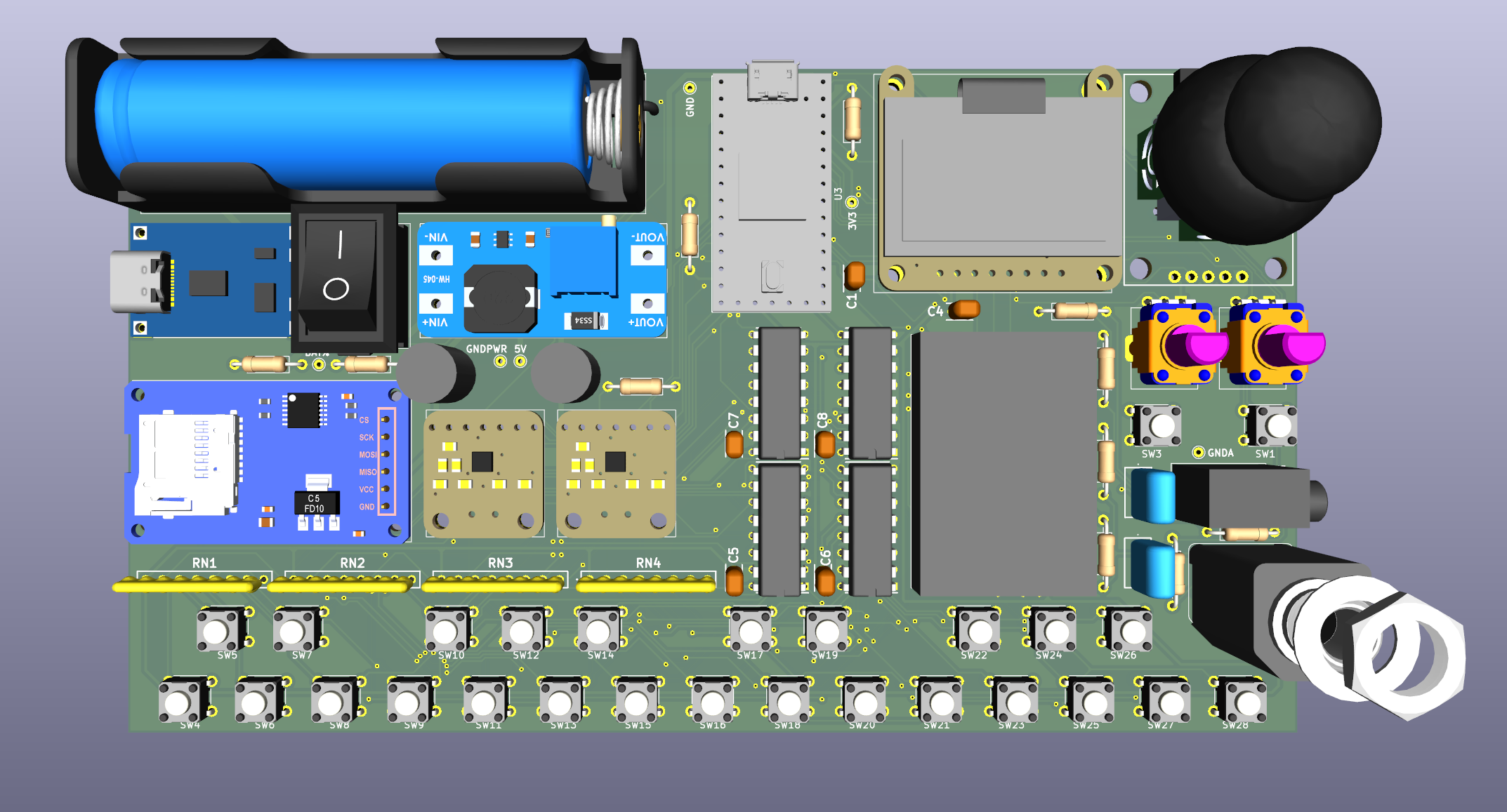
Schematic (full)
Bill of Materials
Core Components
| Component | Quantity | Source | Role in the project |
|---|---|---|---|
| Teensy 4.0 | 1 | PJRC / Mouser | Main MCU. Runs the whole audio engine in DMA-driven I2S plus the UI in the main loop. |
| UDA1334A I2S DAC breakout (Adafruit 3678 / clone) | 1 | eMAG | Stereo analog audio output — feeds the headphone jack and (summed to mono) the guitar amp jack. |
| MAX98357A I2S amp breakout (Adafruit 3006 / clone) | 2 | Temu | One per stereo channel, drives the speakers directly. Their multi-level SD_MODE pin handles both channel selection and dynamic mute. Rework needed: desolder the onboard 1 MΩ SD_MODE pull-up before assembly. |
| Sony SS-TSF550 speakers (4 Ω) | 2 | Local | Stereo speaker output. |
| SN74HC165N shift register | 4 | Mouser | 32 parallel-in / serial-out inputs, daisy-chained, bit-banged on 3 GPIO. Scans the 25 keyboard switches. |
| Bourns 4608X-101-103LF (7× 10 kΩ bussed) | 4 | Mouser | Key pull-up resistor networks (28 resistors total, 25 used for keys, 3 unused). |
| Omron B3F-1000 tactile switch | 27 | Mouser | 25 piano keys + 2 octave buttons (same part for consistent feel). |
| SSD1306 1.3” OLED (Adafruit 938 STEMMA QT) | 1 | Mouser / eMAG | I2C menu display (factory-jumpered for I2C, no rework needed). |
| SparkFun analog joystick (BOB-09110) | 1 | Temu | Pitch bend / modulation in play mode; navigation and numeric editing in menu mode; click activates the menu. |
| Rotary potentiometer (Alps RK09K1130AU2, 10 kΩ linear) | 2 | Mouser / Local | Master volume and FX (LPF cutoff). |
| HW-125 micro SD module | 1 | Temu | Only touched when saving a recorded loop to a WAV file on the card. |
| SJ1-3535NG 3.5 mm stereo jack (switched) | 1 | Mouser | Headphone output. Tip switch is used for plug detection. |
| Switchcraft 112AX 1/4” mono jack (switched) | 1 | Mouser | Guitar amp output. Tip switch is used for plug detection. |
| TP4056 USB-C charger module | 1 | Temu | Li-Ion charging with DW01A overcharge/over-discharge protection (~2 A discharge trip). |
| MT3608 boost converter module | 1 | Temu | 3.7V → 5V DC-DC for the Teensy VIN, both MAX98357A amps, and the SD reader. |
| Samsung INR18650-35E + holder | 1 | Local | ~3500 mAh Li-Ion power source. |
| SPDT rocker switch | 1 | Local / Temu | Master power on/off, sits in series with the battery → MT3608 input. |
| 470 µF aluminium electrolytic (ECA-1AHG471 or equivalent) | 2 | Mouser | Local +5V rail reservoir, one near each MAX98357A — absorbs audio-rate transient current that the MT3608 loop can't track. |
Passive Components (key values)
Resistors:
- 210 kΩ (E96) or 220 kΩ (E24) — R1: MAX98357A-RIGHT
SD_MODEseries resistor for right-channel selection. - 100 kΩ ×2 — R11, R12: battery voltage divider on
BAT_SENSE. - 100 kΩ ×2 — R9, R10: pull-ups for jack detection (
JACK_GUITAR_DET,JACK_HP_DET). - 47 kΩ ×2 — R5, R6: guitar amp output L+R summing network.
- 33 Ω ×2 — R7, R8: headphone output series isolation / short-circuit protection.
- 10 kΩ — R14: HP jack-detect LPF series resistor.
- 4.7 kΩ — R15: guitar jack-detect LPF series resistor.
- 10 kΩ ×2 — post-PCB bring-up rework, soldered point-to-point at each jack: TIP-to-sleeve pulldown to GNDA on each audio output jack. Required because the UDA1334A breakout's onboard 47 µF AC-coupling caps leave the TIP nodes floating at DC, which defeats the tip-switch jack detection. Not present on the schematic — added by hand after the first jack-detect bring-up failed.
- 0 Ω ×2 — R2, R3: ground-domain net ties (
GND–GNDAandGND–GNDPWR).
Capacitors:
- 0.1 µF X7R 50 V MLCC ×~6 — C4 (OLED), C5–C8 (SN74HC165 ×4), C1 (MT3608 output bypass).
- 1 µF X7R MLCC ×2 — C12, C13: jack-detection LPF capacitors.
- 470 µF aluminium electrolytic ×2 — C9, C11: local +5V reservoir at each MAX98357A.
- No external coupling caps on UDA1334A outputs — the breakout already includes 47 µF coupling caps internally.
- No external decoupling caps on MAX98357A breakouts — both already include 10 µF + 0.1 µF on their VIN.
1. Microcontroller — Teensy 4.0
The heart of Mini Synth is a Teensy 4.0 built around the NXP iMXRT1062 ARM Cortex-M7 running at 600 MHz with hardware FPU. It provides 1 MB of RAM, 2 MB of flash, and dedicated I2S audio hardware. The Teensy Audio Library gives me a complete real-time DSP framework — oscillators, filters, mixers, effects, wavetable synthesis — all running on DMA, which leaves the main loop free for UI and control logic.
- All Teensy 4.0 GPIO pins are 3.3 V logic and are NOT 5 V tolerant. Every peripheral has been chosen accordingly.
- The VIN-to-VUSB copper trace on the bottom of the Teensy or the USB cable's red wire must be cut when the board is powered from an external battery, otherwise the USB rail back-feeds into the battery path.
- Debug uses USB
Serial(12 Mbit/s), so IO 0 and IO 1 — which default toSerial1RX/TX — are repurposed as GPIO outputs driving the MAX98357ASD_MODElines. Firmware must therefore never callSerial1.begin().
2. Keyboard — 25 Keys via Shift Registers
The keyboard consists of 25 Omron B3F-1000 tactile switches in a piano-like layout spanning C3 to C5 at zero octave shift (MIDI notes 48..72). The switches are active-LOW: each input is held HIGH by a 10 kΩ pull-up to +3V3 and shorts to GND when pressed. I picked 10 kΩ (rather than 100 kΩ) because mechanical contacts benefit from ~330 µA of “wetting current” to break through any contact oxide — useful for long-term reliability on hand-actuated keys.
The pull-ups are 4× Bourns 4608X-101-103LF bussed resistor networks (RN1–RN4). Each package gives 7× 10 kΩ resistors sharing a common bus pin tied to +3V3 — 28 resistors total, 25 used for the keys, 3 unused. Using bussed networks instead of 25 discrete resistors saves a huge amount of board area.
The 25 keys are scanned via 4× SN74HC165N 8-bit parallel-in/serial-out shift registers (IC4–IC7) daisy-chained. The shift registers are bit-banged on three GPIO pins — DATA on IO 5, CLOCK on IO 8, LATCH on IO 9 — rather than using the hardware SPI peripheral. This was intentional: the hardware SPI bus is reserved for the SD card module. Bit-banging the 74HC165 chain at 600 MHz takes negligible CPU time and avoids any contention. (I do insert a 32-NOP burst between SR clock edges because the Teensy 4.0 can toggle GPIO faster than the SN74HC165's 20 ns minimum pulse width.)
Each shift register has a 0.1 µF X7R bypass capacitor at its VCC pin (C5–C8). Worst-case rail load from the keyboard is ~10 mA — negligible against the Teensy's 250 mA 3.3 V budget.
3. User Controls
Two octave buttons (Omron B3F-1000, SW1 and SW3):
- Oct+ (IO 2): Shifts the keyboard up one octave on each press (clamped to +5).
- Oct− (IO 3): Shifts the keyboard down one octave on each press (clamped to −3).
- Both pressed together = looper transport gesture. A short combo press advances the looper state machine (start a recording, finish a recording, start an overdub, etc.); a long combo hold (≥ 1 s) opens the Save / Clear / Cancel prompt.
They use the Teensy's internal INPUT_PULLUP resistors. Originally I had them on pin-change interrupts, but I had to move them to polled input in Controls::tick() once the combo gesture was added — a single-button press is deferred by 60 ms so the combo detector gets first claim, and that kind of deferral is impossible to do cleanly from an ISR.
SparkFun analog joystick (BOB-09110 breakout, 2-axis + push button) — the primary menu interaction device. Its role changes based on context:
| Context | X-axis (IO 15 / A1) | Y-axis (IO 16 / A2) | Push button (IO 4) |
|---|---|---|---|
| Play mode | Pitch bend (±2 semitones) | Modulation depth (vibrato) | Activates the menu |
| Menu mode, navigating | Right = enter submenu / left = go back / left-hold >500 ms = exit menu | Up / down between rows | Enter edit_mode on a numeric row; toggle on/off on an effect; enter a submenu on a category |
Menu mode, edit_mode active | Left = decrement / Right = increment, auto-repeat with acceleration | Up / Down also exit edit_mode | Confirm and exit edit_mode |
This split — “the joystick navigates and edits, the volume pot only ever touches master volume” — is on purpose. An earlier version used the VOL pot to edit menu values, which meant tweaking ADSR in the menu also faded out master volume in the background. The current scheme keeps the two cleanly separated.
The joystick is powered from 3.3 V (never 5 V) so the analog wiper output stays inside the Teensy's ADC range. The pushbutton is held HIGH by the internal INPUT_PULLUP, and unlike the octave buttons it's still on a pin-change ISR — single clicks are timing-critical and benefit from the immediate latch.
Two rotary potentiometers (Alps RK09K1130AU2, 10 kΩ linear):
- Volume pot (IO 17 / A3 —
VOL_POT): Master volume in play mode. Never read in menu mode. Master volume is not even persisted across reboots — every boot it inherits whatever position the knob is in. The knob is the truth. - FX pot (IO 22 / A8 —
FX_POT): Always-live LPF cutoff (logarithmic 20 Hz – 20 kHz) when the Filter effect is enabled in the Effects menu. While Filter is disabled, the cutoff is pinned at 20 kHz and pot motion is ignored. When the user is actively turning the FX pot, the play-HUD's bottom bar swaps from showing VOL to showing the LPF cutoff position for ~2 s so the sweep is visible.
Both pots are powered from +3V3 (high) and GND (low). The RK09K series has two metal anchor tabs tied to the threaded bushing — both are soldered to digital GND pads for mechanical anchoring, finger-capacitance shielding, and ESD protection.
4. Audio Output — Triple I2S Architecture
Mini Synth uses a shared I2S bus with three audio devices receiving the same digital stereo stream from the Teensy's I2S1 port:
Teensy 4.0 I2S1 Outputs:
  IO 7  (OUT1A / DIN)   ──┬──▶ UDA1334A DIN
                           ├──▶ MAX98357A-LEFT DIN
                           └──▶ MAX98357A-RIGHT DIN

  IO 20 (LRCLK1 / WSEL) ──┬──▶ UDA1334A WSEL
                           ├──▶ MAX98357A-LEFT LRCLK
                           └──▶ MAX98357A-RIGHT LRCLK

  IO 21 (BCLK1)         ──┬──▶ UDA1334A BCLK
                           ├──▶ MAX98357A-LEFT BCLK
                           └──▶ MAX98357A-RIGHT BCLK
No MCLK connection is needed: the UDA1334A has an internal PLL that regenerates the system clock from the WSEL signal, and the MAX98357A datasheet explicitly states “No MCLK Required.”
UDA1334A I2S Stereo DAC (Adafruit 3678 breakout / IC3)
Converts the digital I2S stream to analog line-level stereo, feeding the headphone jack and the guitar-amp output path. Powered from +3V3 (the breakout's onboard LDO ends up in dropout, acting as a clean pass-through). The breakout already includes 47 µF AC-coupling capacitors on LOUT/ROUT, so no external coupling caps are added. Configured for I2S format, audio mode (PLL0 = LOW), 44.1 kHz.
GNDA, while the GND pin (pin 3) connects to digital ground GND. This routes the chip's analog reference current away from any digital switching noise. See §8 for the full three-domain ground architecture.
2× MAX98357A I2S Class-D Amplifiers (Adafruit 3006 breakout / IC1, IC2)
Each breakout includes a complete I2S decoder and 3.2 W Class-D amplifier in a single chip. Powered from +5V and accept 3.3 V logic on all digital inputs. Each amplifier directly drives one speaker — filterless Class-D, no external output capacitors needed.
Gain: 9 dB (default — GAIN pin left floating per Adafruit's factory configuration). Combined with firmware-side limiting of the I2S signal to 70 % of full scale, this caps each amplifier's worst-case output power at ~1.5 W instead of 3.2 W — keeps battery current safely under the TP4056 module's ~2 A discharge protection threshold.
Local bulk capacitance. One 470 µF aluminium electrolytic (C9, C11) is placed locally on the +5V rail at each MAX98357A breakout. These absorb the audio-rate transient current swings (50 Hz – 1 kHz) that the MT3608's regulation loop can't track quickly enough during loud sustained chords.
Channel selection via SD_MODE (datasheet Table 5)
The MAX98357A's SD_MODE pin is not a simple digital shutdown input — it's a multi-level analog sense input that does both shutdown control and channel selection at the same time:
SD_MODE voltage | Mode | Selected output |
|---|---|---|
| Below B0 (typ 0.16 V) | Shutdown | Output stage Hi-Z, ≈0.6 µA quiescent |
| Between B0 and B1 (typ 0.16–0.77 V) | Active | (L + R) / 2 mono mix |
| Between B1 and B2 (typ 0.77–1.4 V) | Active | Right channel |
| Above B2 (typ 1.4 V) | Active | Left channel |
For VDDIO = 3.3 V (Teensy GPIO), the datasheet's formula R_SMALL = 94.0 × VDDIO − 100 gives 210 kΩ — the resistor that puts SD_MODE between B1 and B2 (right channel) when the GPIO is HIGH.
SD_MODE and the chip's V_DD (5 V). This must be desoldered from each breakout before installation — otherwise the GPIO LOW state would fight the pull-up and shutdown never engages. Once removed, only the chip's internal 100 kΩ pull-down remains.
Wiring
LEFT amp:   Teensy IO 0  ────────────────────────▶  MAX98357A-LEFT  SD_MODE
RIGHT amp:  Teensy IO 1  ──[ 210 kΩ (R1) ]───────▶  MAX98357A-RIGHT SD_MODE
| IO 0 (LEFT) | IO 1 (RIGHT) | V_SD_MODE LEFT | V_SD_MODE RIGHT | Result |
|---|---|---|---|---|
| HIGH (3.3 V) | HIGH (3.3 V) | 3.3 V (above B2) | 3.3 × 100/(210+100) = 1.06 V (between B1 and B2) | Stereo: L on left amp, R on right amp |
| LOW (0 V) | LOW (0 V) | 0 V (below B0) | 0 V (below B0) | Both amps in shutdown — speakers fully muted |
This single mechanism handles both channel selection (set at design time by the resistor) and dynamic mute (controlled by the GPIOs from firmware).
Power-on sequencing. During the brief MCU-boot window before setup() runs, both Teensy GPIOs are high-Z. With the breakout's 1 MΩ pull-up removed, only the chip's internal 100 kΩ pull-down remains active — both SD_MODE pins sit at 0 V, so both amps come up in shutdown automatically. The firmware then writes LOW explicitly, configures the I2S chain, and only drives the lines HIGH once AudioEngine::isReady() has confirmed the I2S DMA pipeline has flushed with at least 5 valid silent audio blocks (~15 ms). No audible pop or click at boot.
Hardware mute on jack insertion. When a headphone or guitar-amp plug is detected, the firmware drives both IO 0 and IO 1 LOW — putting both amplifiers into hardware shutdown. This is cleaner than software muting because the MAX98357A handles its own output-stage transition gracefully (no pop), the CPU doesn't have to keep zeroing buffers, and quiescent current per chip drops to ~0.6 µA — extending battery life when a plug is left inserted.
5. Audio Output Paths
Headphone Output (SJ1-3535NG 3.5 mm switched stereo jack, U5)
The UDA1334A's analog L/R outputs (already AC-coupled by the breakout's 47 µF caps) pass through 33 Ω series resistors (R7, R8) to the jack's tip and ring; sleeve connects to GNDA. The 33 Ω resistors give:
- Output isolation from headphone-cable capacitance (~100–300 pF/m), preventing potential DAC-output ringing.
- Short-circuit protection — if a TS plug is jammed into the TRS jack and shorts ring to sleeve, the resistor limits current within the UDA1334A's 300 mA short-circuit rating.
The tip switch is normally closed to TIP (no plug) and opens when a plug is fully inserted. Detection is on IO 6 (JACK_HP_DET) with a 100 kΩ pull-up (R10) and a first-order RC LPF (R14 = 10 kΩ, C13 = 1 µF — ~16 Hz cutoff) that rejects audio coupling and debounces plug insertion.
JACK_HP_DET below 1 V — both detect lines sit HIGH whether a plug is inserted or not. With the pulldown fitted, TIP sits at GNDA at DC and the tip switch can properly do its job. The same fix is on the guitar jack too. With both pulldowns in place I set HW_DISABLE_JACK_DETECT back to 0 in Config.h and the jack-detect mute works as designed.
| Plug state | Tip switch | IO 6 reads |
|---|---|---|
| No plug | Closed to TIP (held at GNDA by the 10 kΩ pulldown) | LOW |
| Plug inserted | Open | HIGH (pulled up by R10) |
Guitar Amp Output (Switchcraft 112AX 1/4" switched mono jack, U4)
The stereo L and R outputs are summed to mono via 2× 47 kΩ summing resistors (R5, R6) directly into the 1/4” jack tip. The 47 kΩ resistors current-limit the DAC outputs and isolate them from the typical 1 MΩ guitar-amp input. Sleeve connects to GNDA.
The 112AX's tip switch works exactly the same way as the SJ1-3535NG's: normally closed to TIP with no plug, open when a plug is inserted. Detection on IO 23 (JACK_GUITAR_DET) mirrors the headphone circuit: 100 kΩ pull-up (R9), LPF formed by R15 (4.7 kΩ) and C12 (1 µF). Same 10 kΩ TIP-to-sleeve pulldown rework as on the headphone jack — same reason.
Because both jacks have the same polarity, the firmware mute logic is symmetric:
mute = (digitalRead(JACK_HP_DET) == HIGH) || (digitalRead(JACK_GUITAR_DET) == HIGH);
6. Display — SSD1306 1.3" OLED (Adafruit 938 STEMMA QT, DS1)
An Adafruit 938 SSD1306 128×64 monochrome OLED provides visual feedback for the current instrument, octave, effects, battery level, the menu system, the tempo dot, and the looper count-in overlay. The STEMMA QT revision ships factory-configured for I2C (jumpers J1/J2 closed), has onboard auto-reset and onboard 10 kΩ I2C pull-ups, so no external rework or pull-ups are needed.
Connection: I2C on IO 18 (SDA0) and IO 19 (SCL0), default address 0x3D (factory default for the 128×64 variant). Powered from +3V3 with one 0.1 µF X7R bypass cap (C4). CS, DC/A0, Rst, and 3Vo pins are left NC. The OLED is mounted physically upside-down on the PCB, so Display::begin() calls oled.setRotation(2) to flip the framebuffer in software.
7. Storage — HW-125 Micro SD Card Module (U6)
The HW-125 is used only for exporting recorded loops to WAV files. It connects via the Teensy's hardware SPI bus: CS on IO 10, MOSI on IO 11, MISO on IO 12, SCK on IO 13. Powered from +5V — the onboard regulator and level-shifting buffers output 3.3 V on MISO (safe for the Teensy).
In-session loop content lives in a 440 KB RAM buffer (DMAMEM in OCRAM), not on the card. The SD card is only touched at boot (a one-shot write probe to confirm the Save action will work) and when the user picks Save from the end-of-loop prompt (the loop buffer is dumped to root-level /LOOP_NNN.WAV). This is on purpose — the audio interrupt never has to talk to the SD card, so there's no read/write contention that could glitch the audio.
The SD is initialised at a conservative 4 MHz SPI clock through SdFat:
SD.sdfs.begin(SdSpiConfig(PIN_SD_CS, SHARED_SPI, SD_SCK_MHZ(4)));
The default Arduino SD.begin(pin) uses 16–24 MHz which was unreliable on this HW-125 + 8 GB SDHC combo — read-after-write was coming back corrupted. Slow and reliable beat fast and broken; a typical ~440 KB loop still copies in about a second.
Factory instruments (math waveforms + wavetables) don't require an SD card — they're baked into the firmware.
8. Power System
- Battery: Single 18650 Li-Ion cell (Samsung INR18650-35E, 3.0–4.2 V, ~3500 mAh) in a spring-contact holder (BT1).
- Charging: TP4056 USB-C charger module (U1) — CC/CV Li-Ion charging with DW01A overcharge / over-discharge protection (FS8205A dual N-MOSFET pair, ~2 A discharge trip). USB-C is the charging port; programming uses the Teensy's separate micro-USB.
- Voltage boost: MT3608 DC-DC boost (U2) — 3.0–4.2 V battery → stable 5 V. Powers Teensy VIN (trace cut), both MAX98357A amps, and the HW-125. The Teensy's onboard LDO then derives 3.3 V for all logic.
- Power switch: SPDT rocker switch (SW2) in series with the battery feed to the MT3608 input. The TP4056 sits on the unswitched battery side so the device can still charge while off.
- Bulk capacitance: Two 470 µF aluminium electrolytics (C9, C11), one near each MAX98357A. One small 100 nF MLCC (C1) at the MT3608 output for HF bypass.
Worst-case rail current
Each MAX98357A at 9 dB and 70 % full-scale draws ≤ 0.75 A peak from +5V (~1.5 W into 4 Ω at 85 % efficiency). Both amps plus the rest of the +5V load (Teensy ~100 mA, SD ~100 mA peak) gives ~1.7 A peak on +5V. At V_bat = 3.2 V the MT3608 pulls ~3.2 A from the battery — close to the TP4056's 2 A trip threshold but kept manageable by the two local 470 µF reservoirs absorbing transient peaks and the firmware's 70 % full-scale output cap reducing average current.
Three-domain ground architecture
To prevent high-current speaker return currents from contaminating the audio analog reference and the MCU's digital reference, the schematic uses three distinct ground nets that meet at a single physical star point on the PCB:
| Ground net | Members |
|---|---|
GNDA (analog) | UDA1334A AGND; headphone jack sleeve; guitar-amp jack sleeve; the two 10 kΩ TIP pulldowns I added during bring-up |
GND (digital) | Teensy GND; UDA1334A digital GND; 4× SN74HC165 GND; OLED GND; HW-125 SD GND; joystick GND; potentiometer anchor tabs and low-side; all pull-up bottoms; jack-detect LPF cap returns; battery-sense divider bottom |
GNDPWR (power return) | TP4056 OUT−; MT3608 GND; both MAX98357A GND pins; 470 µF bulk cap negatives (×2); speaker return wires; rocker switch return |
The three nets are joined at a single point via two 0 Ω resistors (R2: GND–GNDA, R3: GND–GNDPWR). The PCB uses a single solid back-layer ground pour — the “star” topology is enforced by component placement (analog jacks far from amps, amps far from MCU) and by the net-tie's location, not by carving the copper plane.
Battery monitoring (''BAT_SENSE'' on IO 14 / A0)
A 100 kΩ / 100 kΩ divider (R11, R12) scales V_bat into the ADC's 0–3.3 V window. V_bat = 4.2 V (full) → V_adc = 2.10 V; V_bat = 3.0 V (low cutoff) → 1.50 V. Continuous drain through the divider is ~21 µA — negligible against a 3500 mAh cell.
Teensy 4.0 Pin Assignment — why each pin is used where it is
This is a denser version of the table you'll see anywhere else, with an extra column on why each pin got picked.
| Teensy IO | Net | Peripheral | Why this pin |
|---|---|---|---|
| 0 | AMP_LEFT_SD | GPIO output | Repurposed from default Serial1 RX. Using USB Serial for debug frees both IO 0 and IO 1 with zero GPIO cost — I needed two GPIOs to drive the two MAX98357A SD_MODE lines and these were the only obvious free pair without breaking another peripheral. HIGH = LEFT channel active, LOW = mute. |
| 1 | AMP_RIGHT_SD | GPIO output | Same story as IO 0. Driven through a 210 kΩ series resistor (R1) so the chip sees a divided voltage between B1 and B2 → right channel. |
| 2 | BTN_OCT_UP | GPIO (polled) | Generic GPIO; nothing special. Originally on pin-change ISR, moved to polled in Controls::tick() once I added the looper combo gesture (needed deterministic 60 ms deferral). |
| 3 | BTN_OCT_DOWN | GPIO (polled) | Same — paired with IO 2 to share the combo state machine. |
| 4 | JOYSTICK_SW | GPIO + pin-change ISR | Single clicks are timing-critical (enter menu, confirm value), so this stays on a pin-change interrupt for the lowest possible latency. INPUT_PULLUP, no external pull-up. |
| 5 | SR_DATA | GPIO (bit-bang) | Generic GPIO for the bit-banged SN74HC165 chain (QH of last chip). Hardware SPI is reserved for the SD card. |
| 6 | JACK_HP_DET | GPIO input | Plain digital input. 100 kΩ pull-up + RC LPF (10 kΩ / 1 µF) — pin chosen mostly for board-layout convenience near the headphone jack. |
| 7 | I2S1_DIN | I2S (OUT1A) | Hard-wired by the Teensy Audio Library's AudioOutputI2S — not a choice. Carries the I2S data stream to the UDA1334A + both MAX98357A. |
| 8 | SR_CLK | GPIO (bit-bang) | Generic GPIO for SN74HC165 clock. |
| 9 | SR_LATCH | GPIO (bit-bang) | Generic GPIO for SN74HC165 SH/LD. |
| 10 | SD_CS | SPI CS | Standard hardware SPI CS pin on the Teensy. The whole SD module uses hardware SPI; that's why the keyboard had to bit-bang. |
| 11 | SD_MOSI | SPI MOSI | Hardware SPI — not a choice. |
| 12 | SD_MISO | SPI MISO | Hardware SPI — not a choice. |
| 13 | SD_SCK | SPI SCK | Hardware SPI — not a choice. Also the Teensy onboard LED, which flashes during SD activity — useful as a free visual debug indicator. |
| 14 / A0 | BAT_SENSE | ADC | First analog pin; 100 kΩ / 100 kΩ divider gives 0.5× ratio (4.2 V → 2.10 V on the ADC). |
| 15 / A1 | JOYSTICK_X | ADC | Joystick X axis — pitch bend in play, navigation/edit in menu. Needs ADC, otherwise pin choice is arbitrary. |
| 16 / A2 | JOYSTICK_Y | ADC | Joystick Y axis — modulation in play, navigation in menu. |
| 17 / A3 | VOL_POT | ADC | Volume pot — needs ADC. |
| 18 / A4 | SDA0 | I2C | Standard hardware I2C bus — not a choice. Talks to the SSD1306 OLED. |
| 19 / A5 | SCL0 | I2C | Standard hardware I2C clock — not a choice. |
| 20 | LRCLK1 | I2S | Hard-wired by AudioOutputI2S — not a choice. |
| 21 | BCLK1 | I2S | Hard-wired by AudioOutputI2S — not a choice. |
| 22 / A8 | FX_POT | ADC | FX pot — needs ADC. Wired up so the Filter effect can sweep the LPF cutoff live. |
| 23 / A9 | JACK_GUITAR_DET | GPIO input | Plain digital input. 100 kΩ pull-up + RC LPF (4.7 kΩ / 1 µF). |
| 24–33 | NC | — | Back-side pads, unused. |
| VIN | +5V input | Power | From MT3608 (Teensy's VIN-VUSB trace / USB cable's red wire cut). |
| GND | Ground | Power | Connected to GND (digital) domain. |
| 3.3V | 3.3V output | Power | From Teensy LDO → shift registers, joystick, both pots, OLED, UDA1334A breakout, all pull-ups, battery-sense divider. |
Photos
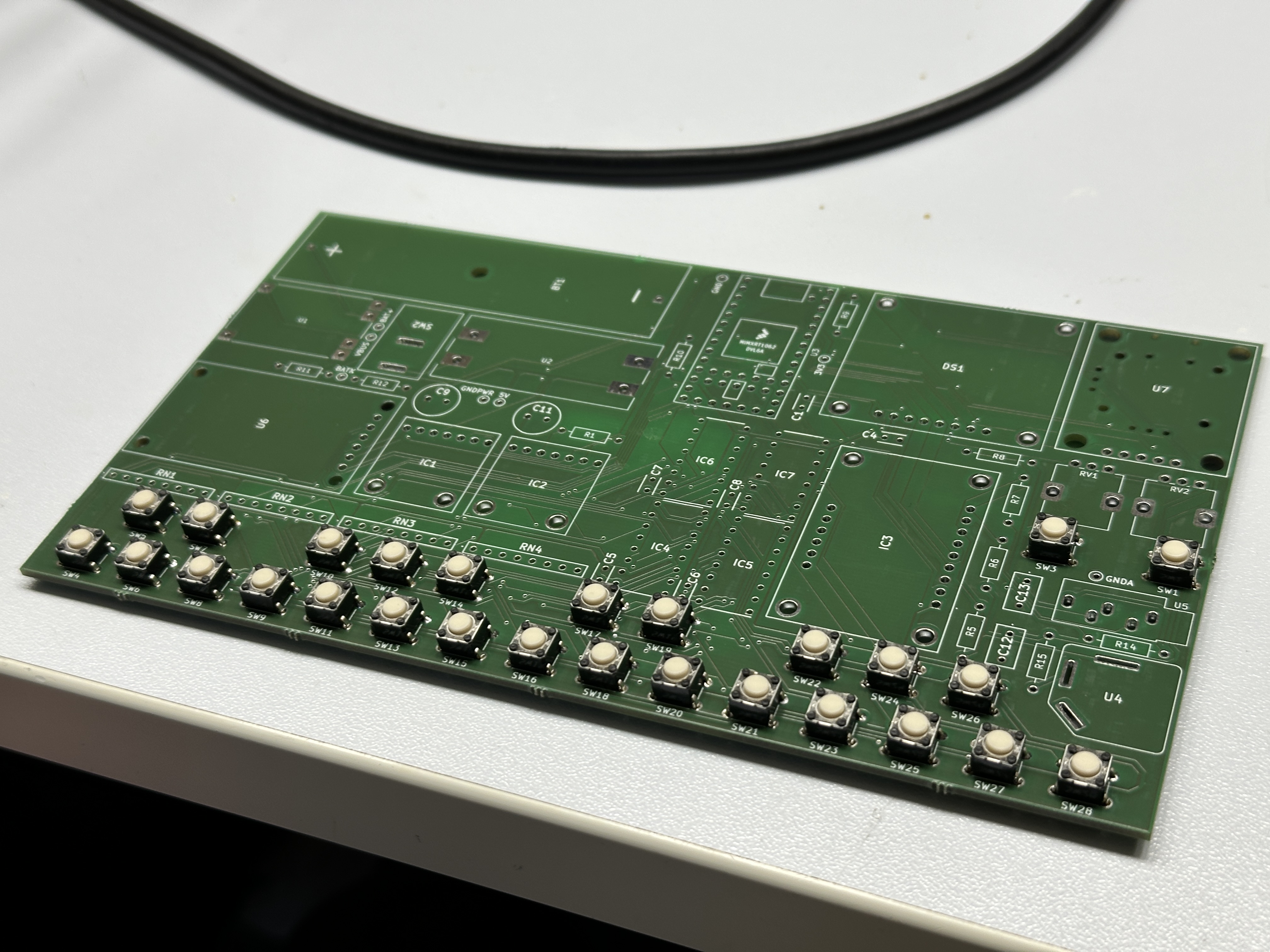
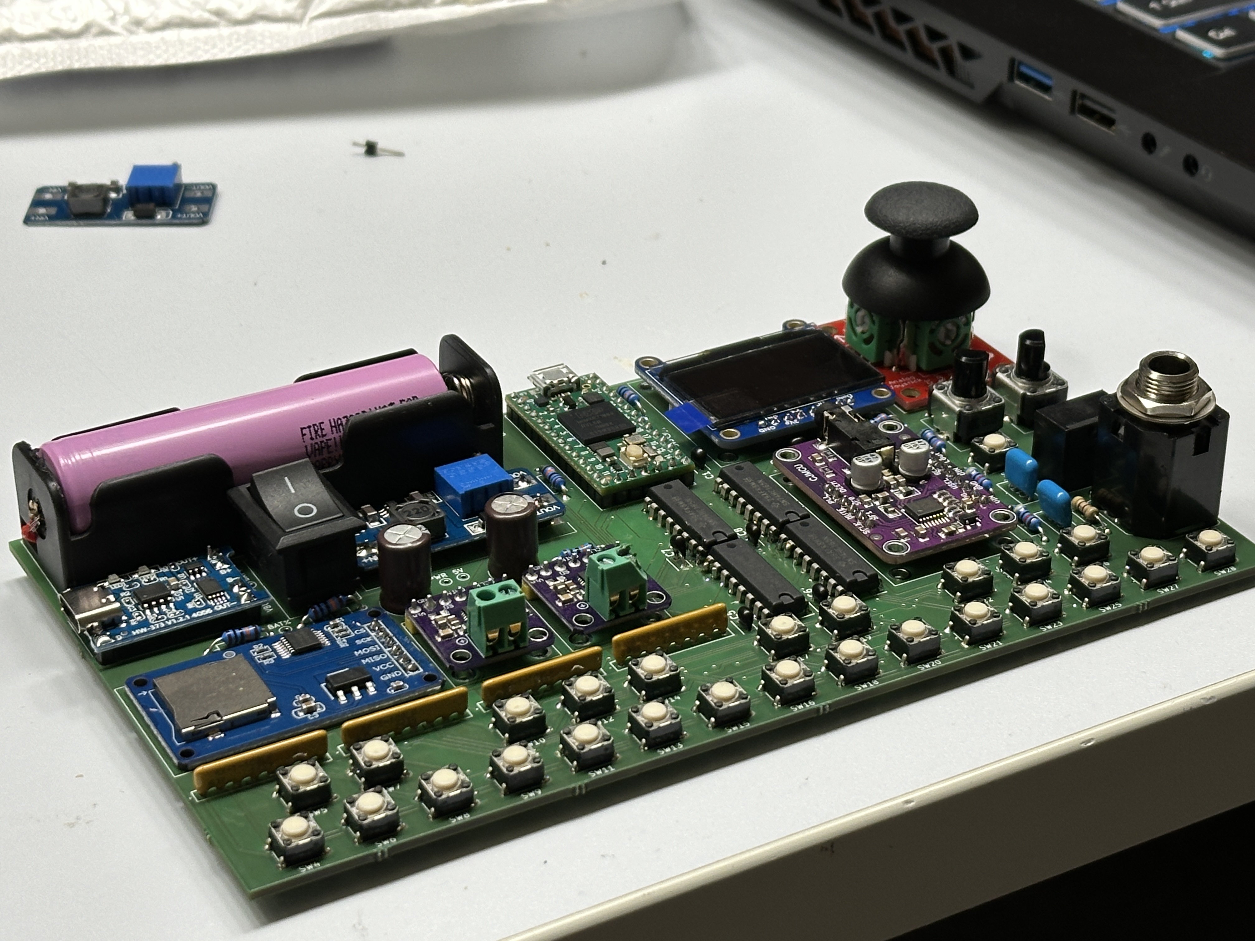
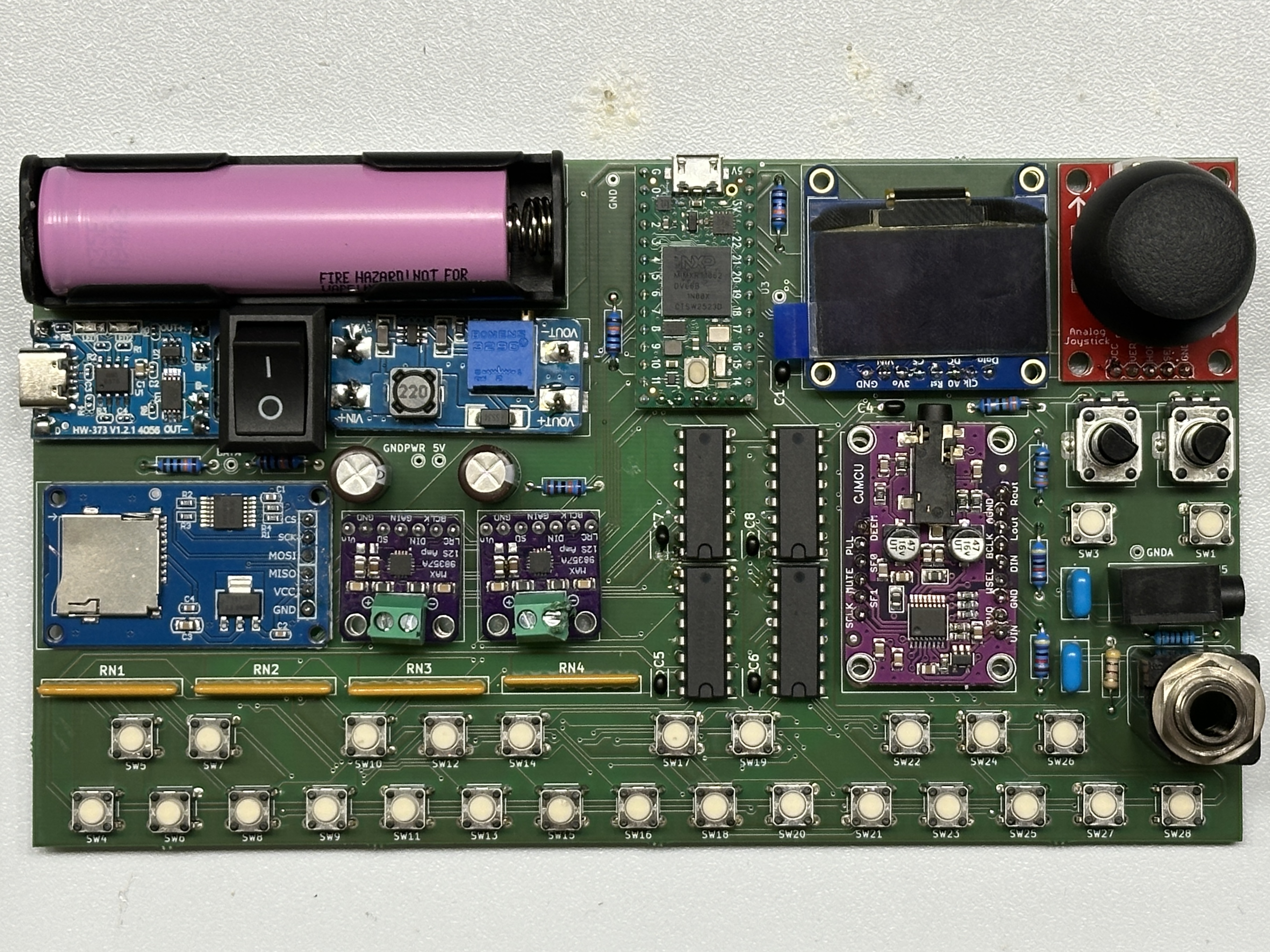
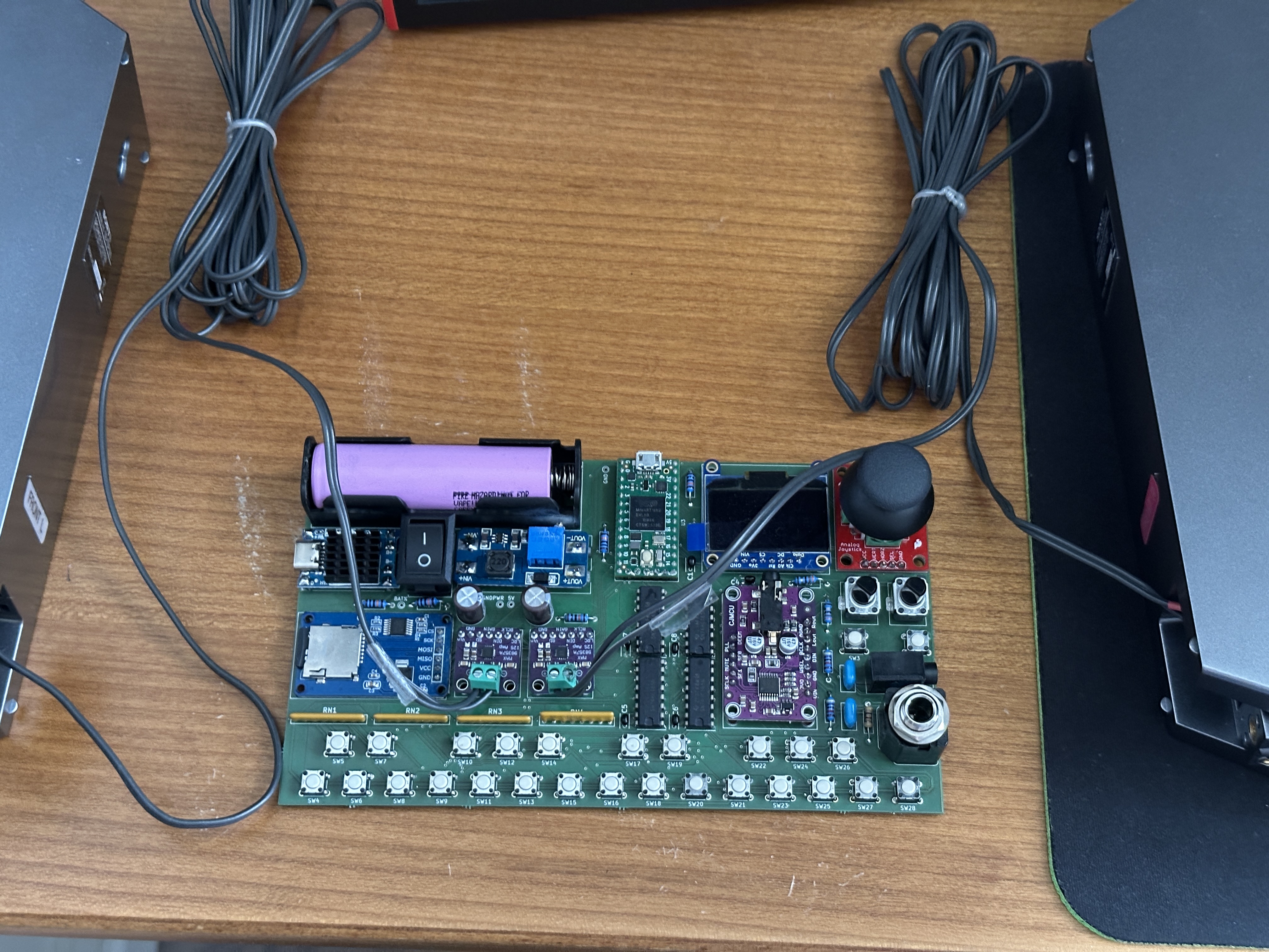
Hardware milestones
- Project proposed. Initial feasibility analysis (does the Teensy 4.0 have the DSP headroom + flash + audio peripherals for an 8-voice synth? Yes).
- BOM finalized; ordered Teensy 4.0, MAX98357A and UDA1334A breakouts, OLED, shift registers, keyswitches, resistor networks, jacks, etc.
- KiCad schematic capture done — MCU, I2S audio chain, keyboard scanning, user controls, power, three-domain ground architecture.
- Schematic review and ERC fixes.
SD_MODEchannel-selection scheme designed (210 kΩ series resistor for right channel, direct GPIO drive for left from the Teensy). - PCB layout in KiCad. Component placement enforces the star-ground topology (analog jacks isolated from amps, amps isolated from MCU).
- PCB sent to Aisler for fabrication.
- PCB arrived. Component assembly + first power-on. Found and fixed the jack-detect issue (added the two 10 kΩ TIP-to-sleeve pulldowns by hand).
- Firmware development.
Software Design
Current implementation status
The firmware is substantially complete — everything described in this section is implemented and working on the assembled board. There are two sketches in the repo:
firmware/MiniSynth/MiniSynth.ino— the production firmware. Modular, namespaced subsystems (AudioEngine, Keyboard, Controls, Display, Menu, Tempo, Looper, Persistence). This is the one in active development.firmware/MiniSynthTest/MiniSynthTest.ino— a single-file diagnostic sketch used during first power-on to verify each peripheral works in isolation. Both speakers stay hard-muted until the user explicitly arms a test tone by holding Oct+ and Oct− for 2 seconds; the tone amplitude is hard-capped at ~−20 dBFS even after arming, so an assembly fault can't accidentally blow a speaker.
Development Environment and Libraries
- IDE: Arduino IDE 2.x with the Teensyduino add-on (PJRC's Teensy core for the Arduino toolchain). Board = Teensy 4.0, USB Type = Serial, CPU Speed = 600 MHz, Optimize = Faster.
- Audio framework: Teensy Audio Library — a complete real-time DSP graph framework that runs at 44.1 kHz / 16-bit via DMA-driven I2S. The graph is wired in code in
AudioEngine.cpp; PJRC's Audio System Design Tool was useful for prototyping individual blocks but cross-translation-unit hooks (the Tempo metronome + Looper record/play queues) had to be hand-coded. - Wavetable conversion: Teensy Wavetable Synthesis / SoundFont Decoder — converts SoundFont (
.sf2) files into C header files with PROGMEMint16_tsample arrays + metadata structs (root note, sample rate, loop region, ADSR defaults). The factory instruments are all compiled in this way. - OLED driver: Adafruit_GFX + Adafruit_SSD1306 (I2C, address
0x3D, falls back to0x3Cif probing 0x3D fails — some clone boards are populated wrong). - SD/FAT:
SdFat(the modern PJRC-recommended SD library), accessed both via the high-levelSD.openwrapper and the lower-levelSD.sdfs.open(…)/FsFileAPI for the loop-save path (so I canpreAllocate()the whole WAV file before writing — see “Optimizations” below).
Why these libraries?
- The Teensy Audio Library is essentially the way to do real-time audio on a Teensy 4. It provides every DSP block I need (envelopes, filters, mixers, effects, wavetable synth, I2S sink) as ready-made AudioStream nodes, and the entire graph runs on DMA-driven 128-sample blocks in the audio interrupt. Writing this from scratch would have been months of work just to match its CPU efficiency.
- SdFat is the only SD library that gave me reliable read-after-write on the HW-125 module + 8 GB SDHC combo I have, once I lowered the SPI clock to 4 MHz. The default Arduino
SD.begin()at 16–24 MHz was corrupting writes. - Adafruit_GFX + Adafruit_SSD1306 are the de-facto standard for 128×64 SSD1306 OLEDs over I2C. The font + bitmap helpers in Adafruit_GFX are exactly what the play HUD and menu UI need.
Element of novelty
The most novel part of the project, compared to other PM/embedded synth projects I've looked at, is the integrated SD-exporting loop pedal running on the same MCU that does the polyphonic synthesis, on the same audio bus, without any extra DSP chip. The way it works:
- The audio graph mixes (live synth post-FX) + (loop playback) into a
masterMixbus. The looper taps the bus's output with anAudioRecordQueue, so what gets captured is exactly what the user is hearing through the speakers (synth + already-laid-down loop), but NOT the metronome (which is summed in further downstream onmaster.port1) and NOT the master-volume gain. This separation is what makes the metronome audible without being recorded and the master volume non-destructive. - The loop buffer is a single 440 KB
DMAMEM int16_t[]array in OCRAM — about 5.1 s of mono PCM. Overdubs are destructive in place: each new overdub writes the (synth + previous loop) mix back into the same buffer, so I never need more than one buffer regardless of how many overdub layers the user piles on. - The custom
LooperPlayerclass (a subclass ofAudioStream) seamlessly loops the buffer — when the playhead hits the end it wraps to 0 in the sameupdate()call, with no audible click. Recording length is bar-quantized to the metronome grid (rounded up to the next 4-beat boundary), so the loop always wraps cleanly on a downbeat and overdubs phase-align automatically. - The whole “is the user trying to record / overdub / save?” gesture detection rides on top of the existing octave-button hardware — pressing both Oct buttons within 60 ms is a combo, single presses are deferred by 60 ms so the combo detector gets first claim. No extra footswitch.
Lab-topic functionalities and where they show up
This project intentionally exercises every major topic from the PM lab. Here's where each one lives in the firmware:
- GPIO — driven everywhere: the 25 keyboard switches via the SN74HC165 chain (bit-banged in
Keyboard.cpp), the 2 octave buttons (polled inControls.cppso the combo detector can defer single shifts), the joystick push-button, the two jack-detect inputs, and the two MAX98357ASD_MODEoutputs. - UART — USB Serial at 115200 baud for debug, 12 Mbit/s with zero GPIO cost (Teensy 4.0 specialty). I never touch hardware Serial1 because IO 0 and IO 1 are repurposed as GPIO outputs.
- Interrupts — the audio DMA path runs entirely in interrupt context; the joystick click is on a pin-change ISR with a 30 ms hardware debounce + 100 ms inter-click gate. The octave buttons used to be on ISRs but moved to polling once I added the combo gesture (a deferred-shift state machine needs deterministic timing — ISRs were racing the polling loop).
- Timers / PWM — the Teensy I2S peripheral generates BCLK + LRCLK from its internal clock; the audio update ISR fires every 2.9 ms (128 samples at 44.1 kHz); the metronome and looper count-in use a
millis()-driven beat scheduler inTempo.cpp. - ADC — five ADC inputs: joystick X/Y (
JOYSTICK_X,JOYSTICK_Y), volume pot (VOL_POT), FX pot (FX_POT), battery voltage (BAT_SENSE). 12-bit resolution, 32× hardware averaging. - SPI — hardware SPI bus dedicated to the HW-125 SD card module at 4 MHz.
- I2C — hardware I2C bus to the SSD1306 OLED at default speed.
Core Audio Engine
The firmware runs the entire audio synthesis on the Teensy Audio Library DSP graph in DMA, leaving the main loop free for UI and control:
- 8-voice polyphony with dynamic voice allocation (oldest-voice stealing when all 8 are occupied; voice count is user-configurable 1–8 in the Settings menu).
- Two sound-generation engines running in parallel:
AudioSynthWaveform/AudioSynthNoiseWhite— math-generated waveforms (sine, sawtooth, square, triangle, pulse, noise). Zero storage cost; generated on demand. ADSR envelopes are user-editable and persist in EEPROM.AudioSynthWavetable— factory wavetable instruments stored in firmware flash (PROGMEM headers). ADSR envelopes are read-only — they come baked into the SoundFont's per-sample fields andAudioSynthWavetabledoesn't let me override them from outsidesetInstrument(). The Envelope page still shows them so the user can see what's going to happen.
- Effects chain: Distortion → Bitcrush → Chorus → Flanger → Delay → Reverb → LPF. Each effect has its own wet/dry bypass mixer so toggling one off is a true pass-through. The “Chorus” block is actually a second
AudioEffectFlangetuned with chorus-style params (long base offset, slow LFO) — the TeensyAudioEffectChorusturned out to be a static comb filter without LFO motion, which sounded dry. The LPF usesAudioFilterBiquadrather than the Chamberlin SVF, because the SVF was numerically unstable when its int32 state saturated on a fast cutoff sweep. - Scale-aware tuning — in addition to standard concert pitch (A4 = 432–448 Hz, configurable), the synth can be locked to a musical scale (Chromatic, Major, Minor, Pentatonic, Blues, Dorian) with a configurable root note. When a non-chromatic scale is active, each key press snaps to the nearest scale degree — useful for jam sessions and improvisation, “no wrong notes”.
- Hardware speaker muting via
SD_MODE— firmware drives IO 0 and IO 1 LOW on plug detect, plus during boot before the I2S DMA pipeline has flushed with valid silent blocks.
Factory Instruments — Wavetable Synthesis
Factory sampled instruments are compiled into the firmware as C header files generated by the SoundFont Decoder from SoundFont (.sf2) files. Each file is a PROGMEM int16_t sample array plus an AudioSynthWavetable::instrument_data metadata struct that maps each sample to a root note, sample rate, loop region, and ADSR defaults. The set currently compiled in:
| Category | Instruments |
|---|---|
| Piano | Grand Piano, CP-80 EP, Rhodes EP |
| Strings | Violin, Synth Strings |
| Brass | Trumpet, Synth Brass |
| Mallets | Celeste, Vibraphone, Kalimba, Tinkling Bells, Synth Mallet |
| Synth | Bright Saw, Mystery Pad, Solo Vox, Space Voice |
| Drums | TR-808 (kit: Kick, Snare, Clap, Closed Hat, Open Hat, Cymbal — each its own SoundFont sample mapped to a specific MIDI range) |
Looper — RAM-Buffered Loop Pedal
The looper is one of the biggest features and the most fun to play with. State machine:
IDLE ─trigger─▶ ARMED ─count-in─▶ RECORDING ─trigger─▶ PLAYING
                                                          │ ▲
                                                          │ │ trigger
                                                  trigger │ │
                                                          ▼ │
                                                   ARMED_OVERDUB
                                                          │
                                                         wrap
                                                          ▼
                                                       OVERDUB

PLAYING / OVERDUB ─long-hold trigger─▶ END_PROMPT
                                      Save / Clear / Cancel
- Transport = Oct+ & Oct− pressed together. Short combo press = advance state. Long combo hold (≥ 1 s) = open the end-of-loop prompt.
- 4-beat count-in before the first recording (3 → 2 → 1 → GO!) locked to the current BPM. Big size-7 digits over the whole HUD so the player can see them across the room.
- Bar-quantized stop — when the user hits the combo to end recording, the loop length is rounded up to the next 4-beat bar boundary. This keeps the loop and the metronome grid phase-locked, so every wrap lands on a downbeat and overdubs slot in cleanly.
- Destructive overdub — each overdub overwrites the in-RAM buffer with the (live synth + previous loop) mix coming through
masterMix. No additional buffer needed regardless of layer count. - Save — picks the next free
/LOOP_NNN.WAV(linear scan from 001), pre-allocates the file with SdFat, writes the 44-byte WAV header in one call, then streams the loop buffer in 64 KB chunks. Each chunk repaints the splash with percent done so the user sees the save progressing instead of a frozen screen. ~440 KB loop saves in about a second at 4 MHz SPI.
Metronome + Tempo
A separate Tempo page in the root menu exposes:
- BPM (40–240, default 100). Editable with the joystick. Locked while a loop is in flight (the loop was recorded at the previous BPM and would no longer match the metronome grid) — the locked value is suffixed with
*in the UI. - Metronome on/off toggle. Persisted in the looper-config EEPROM blob.
- Volume (0–100 %, default 30 %) for the metronome's level into
master.port1. Decoupled from master volume so you can keep a steady click audible while the synth itself fades in and out.
The metronome path is a tiny audio sub-graph: AudioSynthWaveform (2 kHz on off-beats, 3 kHz on the downbeat of each 4/4 bar) → AudioEffectEnvelope (2 ms attack, 40 ms decay, 0 sustain, 5 ms release) → master.port1. Because master.port1 is downstream of the looper record tap on masterMix, the metronome is audible but NEVER recorded.
Even when the user has the metronome turned off for normal play, the looper force-engages it during ARMED, RECORDING, and OVERDUB so the player always has an audible timing reference during recording.
Persistence — Two-blob EEPROM Layout
Settings are stored in the Teensy's emulated EEPROM. There are two independently-versioned blobs:
- Main blob at offset 0 (magic
MNSY, VERSION 4). Holds voice count, concert pitch, scale, root note, effect-enabled bits, last selected instrument, and 24 slots of factory-instrument ADSR envelopes. - Looper-config blob at offset 512 (magic
LPCF, VERSION 2). Holds the tempo BPM, the metronome on/off flag, and the metronome volume.
The split is on purpose. Bumping a blob's VERSION wipes its contents on the next boot (the firmware detects the mismatch and re-initialises to defaults). By putting tempo / metronome in their own blob, I can add looper-related fields without forcing a VERSION bump on the main blob — which would wipe every user's saved envelopes the first time they install the new firmware. Same idea in reverse: a factory-reset from the Settings menu only wipes the main blob, so a user's BPM / metronome choice is preserved when they hit “Reset defaults”.
Each blob has its own dirty flag + 2-second debounce. Persistence::saveIfDirty() is called every loop iteration and only commits when a blob has been quiet for 2 s, so a sequence of rapid edits (e.g. dragging the joystick to set decay) doesn't write to flash for every step.
Menu System
Activation and Exit
| Action | Trigger |
|---|---|
| Enter menu | Single click of the joystick push-button (in play mode) |
| Exit menu | (a) joystick-left until cursor is at the root, then one more left press; OR (b) hold joystick-left for >500 ms from anywhere in the hierarchy (suppressed while a value is in edit_mode) |
While in menu mode the keyboard is silenced — but the Oct+ & Oct− combo gesture is still polled, so the looper transport still works from any menu page.
Navigation rules
This is the most important UI convention of the firmware:
| Item type | Click | Right | Left | Left/Right while editing |
|---|---|---|---|---|
| Category | Enter submenu | Enter submenu | Go to parent | — |
| Instrument terminal | Select | Open Envelope page | Go to parent | — |
| Effect terminal | Toggle ON / OFF | (no effect) | Go to parent | — |
| Numeric / enum row | Enter edit_mode (value gets < > brackets) | Enter edit_mode | Go to parent (only when not editing) | Decrement / increment, auto-repeat after 400 ms with acceleration at 800 ms |
| Read-only row (Battery, wavetable Envelope) | (no effect) | (no effect) | Go to parent | — |
Key principle: the joystick navigates and edits, the VOL pot only ever touches master volume. They are not mixed up. An earlier version used the pot to edit menu values and that caused exactly the surprise it sounds like (tweaking ADSR also faded out the synth in the background).
Menu hierarchy
ROOT
├── Instruments
│   ├── Waveforms (math-generated, in firmware)
│   │   ├── Sine / Sawtooth / Square / Triangle / Pulse / Noise
│   │   ├── (click selects, right opens an editable Envelope page)
│   ├── Piano       (Grand Piano, CP-80 EP, Rhodes EP)
│   ├── Strings     (Violin, Synth Strings)
│   ├── Brass       (Trumpet, Synth Brass)
│   ├── Mallets     (Celeste, Vibraphone, Kalimba, Tinkling Bells, Synth Mallet)
│   ├── Synth       (Bright Saw, Mystery Pad, Solo Vox, Space Voice)
│   └── Drums       (TR-808)
│   │   (click selects, right opens a READ-ONLY Envelope page)
│
├── Envelope         (per-selected-instrument; editable for waveforms,
│                     read-only for wavetable instruments)
│   ├── Attack       (click → edit_mode → joystick L/R 0–5000 ms)
│   ├── Decay
│   ├── Sustain     (0–100 %)
│   └── Release
│
├── Effects (each row toggles on click)
│   ├── Reverb
│   ├── Delay
│   ├── Chorus
│   ├── Flanger
│   ├── Bitcrush
│   ├── Distortion
│   └── Filter   (FX-pot LPF; enabling routes the pot to LPF cutoff)
│
├── Tempo
│   ├── BPM         (joystick L/R 40–240; locked while looper active)
│   ├── Metronome   (click toggles ON / OFF)
│   └── Volume      (joystick L/R 0–100 %; independent of master volume)
│
└── Settings
    ├── Voice Count   (joystick L/R 1–8)
    ├── Tuning
    │   ├── Concert Pitch (joystick L/R 432–448 Hz)
    │   ├── Scale         (joystick L/R: Chromatic, Major, Minor, Pentatonic, Blues, Dorian)
    │   └── Root          (joystick L/R: C, C#, D, D#, E, F, F#, G, G#, A, A#, B)
    ├── Battery     (read-only: voltage + estimated %)
    └── Reset       (factory reset — opens a Cancel / Reset confirm prompt)
Master Volume is intentionally not in the menu — the VOL pot is the only way to change it, and it's not persisted. Putting it in the menu as well caused exactly the kind of “menu fights the knob” UX bug it was supposed to avoid.
Boot Sequence
On power-up, the OLED shows a splash screen (“Mini Synth / Loading…”) with a progress bar while firmware:
- Brings up the Display and shows a brand-only splash for 1.5 s so the user actually sees the device name.
- Initialises the I2S audio chain (with both amps held in
SD_MODEshutdown until ready). Waits 20 ms while the I2S DMA flushes with silence behind the splash. - Initialises Controls (button polling + joystick centre calibration + ADC averaging + initial pot smoothing).
- Initialises the Keyboard scanner.
- Loads persisted settings + restores the last-selected instrument from the main EEPROM blob.
- Initialises Tempo (loads BPM, metronome enable, metronome volume from the looper-config EEPROM blob).
- Initialises the Looper (mounts the SD card via SdFat at 4 MHz, runs a write-probe to confirm Save will work).
- Hands off to Menu, which raises the SD_MODE lines HIGH once
AudioEngine::isReady()returns true and switches the OLED to play-mode HUD.
Boot time is typically under 2 s. The splash hides the I2S settle window and the SD probe; nothing audible can happen until the speakers are intentionally un-muted.
Runtime model — how all the subsystems fit together
loop() is non-blocking with fixed-cadence ticks:
| What | Cadence | What it does |
|---|---|---|
Controls::tick() | every 5 ms | ADC smoothing + button polling + combo state machine + joystick edges + hold detection |
Keyboard::scan() | every 2 ms | Bit-bang the SN74HC165 chain + 2-pass debounce + stuck-key watchdog |
Menu::tick() | every loop | UI mode dispatch + Display refresh + amp mute decision + looper trigger dispatch |
AudioEngine::tick() | every 5 ms | Vibrato modulation + filter cutoff push + boot-ready gate |
Tempo::tick() | every loop | millis() beat scheduler; fires the metronome envelope on each beat |
Looper::tick() | every loop | Drains the record queue into the RAM loop buffer; advances state on count-in beats + loop wraps |
Persistence::saveIfDirty() | every loop | No-op until 2 s after the last mutation (covers BOTH EEPROM blobs) |
Actual audio playback is DMA-driven by the Teensy Audio Library and runs independently of loop(). Anything in loop() that blocks for more than a few hundred microseconds will starve the menu/keyboard responsiveness — I'm very careful about this. The only intentionally-blocking operation is the SD write in Looper::endChoice(END_SAVE) (the user explicitly asked to save and wants it to finish); even there, the splash is repainted every 64 KB so the UI doesn't look frozen.
Calibration
There are several places where the firmware self-calibrates or applies calibration constants:
- Joystick centre calibration.
Controls::begin()averages 16 samples (~30 ms) of the X and Y axes with the joystick at rest, and stores those as the calibrated centre. This compensates for the BOB-09110's mechanical centre not being exactly at ADC 2048. After calibration, joystick math is asymmetric — full deflection in either direction reaches exactly ±1.0 even if the calibrated centre isn't at the midpoint. - Joystick deadzone + saturation. Inside
Controls::tick(), the centred axis value passes throughapplyDeadzone()which maps |raw| from[JOY_DEADZONE=0.10, JOY_SATURATION=0.95]linearly to[0, 1]. Below the deadzone the axis reads 0 (ignored noise around centre); above the saturation it reads exactly ±1.0 (so the user gets full deflection even if the wiper only reaches ~95 % of Vcc). - Pot smoothing + hysteresis. Each pot reading is IIR-smoothed (
0.70 × previous + 0.30 × current) and then the displayed 0–100 % integer is updated through a Schmitt-trigger style hysteresis band: the integer bin only changes when the smoothed raw value moves more than 0.30 % past the current bin's natural boundary. Without this, ADC LSB noise made the displayed percent dance between adjacent values. Same approach (with H = 0.40) is applied to the displayed battery voltage and percent, which used to dance between 4.16 V ↔ 4.17 V and 95 % ↔ 96 %. - Pot extreme snap.
volPot()/fxPot()snap to exactly 0 below 0.005 and exactly 1 above 0.995. This gives the user a hard reachable min/max within the last ~1° of pot travel — without it, ADC dither at the extremes left envelope parameters with non-deterministic minima (decay would settle to 6 ms one time and 20 ms the next on “fully turned left”). - Battery ADC settling. The
BAT_SENSEdivider has a ~50 kΩ source impedance, near the upper end of what the iMXRT's S/H cap can settle in one conversion after switching from a much lower-impedance channel (the FX pot). I take a throwawayanalogRead(PIN_BAT_SENSE)first to let the S/H cap discharge, then use the second read. The displayed voltage is then IIR-smoothed (3-sample tau) before going through the hysteresis band — initialised from the very first good read so the displayed voltage is correct from boot rather than slowly converging. - Battery voltage divider calibration.
DIVIDER_RATIO = 0.5fandADC_REF = 3.30fare constants inConfig.h. They could be replaced by a single-point calibration constant set per assembled unit (with a multimeter) to compensate for ±1 % resistor tolerance + LDO reference variation — currently the default values give voltage readings within ±50 mV of a multimeter on my unit, which is fine for the “remaining battery %” use case.
Optimizations (and why I needed them)
- Bit-banged shift register scan with a hard 32-NOP pad between clock edges. The Teensy 4.0 can toggle GPIO faster than the SN74HC165's 20 ns minimum pulse width, so a naive bit-bang would violate setup/hold timing and miss bits.
Keyboard::srTimingPad()inserts ~50 ns of NOPs between edges — slow enough for the part, still fast enough that scanning all 25 keys takes a tiny fraction of a millisecond. - Asymmetric stuck-key watchdog in the keyboard scanner. Per-key integrator: +4 on a scan that disagrees with the latched stable state, −1 on agreement, force-flip at count 250. Catches a key whose debounced state got stuck “pressed” due to a noise burst, costs ~zero per scan.
- 2-pass debounce on every key. The raw shift-register bits go through 2 consecutive matching scans before flipping the latched state. This is enough to eliminate the contact bounce of B3F-1000 switches at the 2 ms scan period.
- AudioMemory(200) sized for the real graph + the record queue's worst case. Sizing the block pool too small starves the audio interrupt and causes audible glitches; too large wastes OCRAM. The graph normally uses ~80 blocks in flight, the delay effect needs another ~76, the record queue can hit ~5 during steady-state — 200 is the right ceiling and leaves ~120 KB of OCRAM for the 440 KB loop buffer plus the audio system itself.
AudioEngine::isReady()boot-settle gate. Amps are physically muted (SD_MODE = LOW) until the I2S DMA pipeline has flushed with at least 5 valid silent audio blocks (~15 ms). Without this gate, the boot-time garbage in the uninitialised DMA buffers would, at 9 dB amp gain into 4 Ω, draw peak current near the TP4056's 2 A trip threshold AND make a loud pop.- EEPROM write debouncing.
Persistence::saveIfDirty()delays commits by 2 s after the last mutation. Without this, dragging the joystick to adjust an envelope parameter would burn EEPROM endurance on every step of the joystick auto-repeat. - Flash splash repaints during loop save.
Looper::saveCurrentLoopAsWav()streams in 64 KB chunks and repaintsDisplay::splash(pct, “Saving WAV”)between chunks — without it, the multi-second save looks like a freeze and the user starts pressing buttons. - SdFat
preAllocate()the entire WAV file before writing it. This was the fix to a really annoying bug: building the 44-byte WAV header with ten smalldst.write()calls plus then writing bulk audio caused SdFat's internal sector cache to wedge somewhere between sectors. Switching to (a) pre-allocate the full file size, (b) write the header in one 44-bytewrite(), © stream audio in 64 KB chunks made the bug disappear entirely. Pre-allocation extends the cluster chain BEFORE the data writes, so each subsequent write is just a sector update with no mid-stream FAT entry updates. - HW-125 SPI clock dropped to 4 MHz. The default
SD.begin(pin)uses 16–24 MHz which proved unreliable on the specific HW-125 + 8 GB SDHC combo I have. I switched toSD.sdfs.begin(SdSpiConfig(PIN_SD_CS, SHARED_SPI, SD_SCK_MHZ(4))). Slow + reliable beats fast + corrupted. - Looper RAM-buffered, not SD-buffered. An earlier version of the looper kept the in-session loop as two ping-pong RAW files on the SD card, with simultaneous read + write during overdub. The Teensy would freeze mid-overdub because SD activity in the audio interrupt was contending with SD activity in
loop(). Moving the in-session buffer to RAM and only touching SD on Save fixed this completely — at the cost of a fixed 5.1 s max loop length, which is fine for the use case. - Cross-TU
AudioConnection.connect()deferred tobegin(). A really subtle static-init-order trap: constructor-timeAudioConnections that cross translation units (e.g. the Tempo's metronome → master mixer link, wheremasterlives inAudioEngine.cpp) get silently dropped by the destination AudioStream's constructor running later and resetting its destination_list to NULL. Fix: default-construct the cross-TU connections and callconnect(…)from inside the namespace'sbegin()function, after all globals have constructed. Used in bothTempo.cppandLooper.cpp. - Looper count-in and overdub force the metronome on. Even if the user normally plays without a metronome,
Looper::enterArmed()andenterArmedOverdub()callTempo::setForceMetronome(true)so the count-in beeps are audible and the overdub gets a tempo reference. Reverted to the user's setting on entering PLAYING.
Validation — how I know it works
- Per-subsystem manual test. Both speakers play test tones from
MiniSynthTest.ino(the diagnostic sketch). All 25 keys + 2 octave buttons trigger Serial-Monitor prints. The OLED renders. The SD card mounts and the write-probe succeeds. Battery voltage shown on the HUD matches a multimeter on the BAT+ test point. - Live audio path test. Plug in headphones, plug in a guitar amp — jack-detect mutes the speakers in both cases (after the 10 kΩ TIP-pulldown rework), audio comes out the relevant jack cleanly.
- 8-voice polyphony test. Press 8 keys simultaneously, confirm all 8 voices ring and that the 9th press steals the oldest voice without a click.
- Effects chain test. Toggle each effect on/off in the Effects menu and confirm the audible character changes only when that one effect is flipped. Sweep the FX pot with Filter enabled and confirm a smooth log LPF sweep from 20 Hz to 20 kHz.
- Looper test. Start a loop with the Oct+&Oct− combo, play a 4-bar phrase, finish the loop. Phrase plays back cleanly with no click at the wrap. Overdub a second layer, third layer — they all phase-align to the loop downbeat. Save with the long combo hold, copy the resulting
/LOOP_001.WAVoff the card, open it in Audacity — the file is a valid 44.1 kHz / mono / 16-bit WAV that plays back identically to what came out of the speakers. - Metronome test. Toggle metronome on, confirm a steady audible beat. Change BPM with the joystick, confirm the beat speed changes. Verify the downbeat has a higher-pitched click than the off-beats.
- Persistence test. Change envelope values, voice count, tuning. Power-cycle. Confirm all values come back exactly as set.
- Reset defaults test. Settings → Reset → Reset. Confirm voice count = 8, concert pitch = 440 Hz, scale = Chromatic, all effects off, sine waveform selected. Confirm BPM / metronome / metronome volume are NOT reset (the looper EEPROM blob is intentionally preserved).
Demo videos
Results
The expected (and at this point largely-achieved) results are:
- Fully functional, battery-powered, 25-key polyphonic synthesizer with onboard stereo speakers, headphone and guitar-amp outputs.
- Both sound-generation engines working (math waveforms + factory wavetables) with up to 8-voice polyphony.
- Full menu hierarchy navigable via joystick + click, with all numeric editing done via the joystick's
edit_modeflow. - Per-instrument ADSR envelopes editable for math waveforms (and persisted in EEPROM); read-only display for wavetable instruments (SoundFont-baked values).
- Configurable effects chain working — each effect can be toggled independently and the Filter effect is sweepable live with the FX pot.
- Scale-aware tuning working — the keyboard snaps to the chosen scale when set to a non-chromatic mode.
- Configurable tempo (40–240 BPM) and metronome on/off, plus an independent metronome volume slider.
- One-button looper feature working: 4-beat count-in, bar-quantized record stop, destructive overdub, save to SD as a 44.1 kHz / mono / 16-bit WAV file.
- Hardware mute on jack insertion (via the
SD_MODEGPIO scheme + the 10 kΩ TIP-pulldown rework) with no audible pop or click on plug events. - Factory reset option in Settings that wipes the main EEPROM blob without touching the user's tempo / metronome preferences.
- Battery life on the order of several hours of continuous play from a single 18650 cell.
- Custom PCB working as designed, with the three-domain ground architecture delivering a clean audio output free of digital noise.
Conclusions
The Mini Synth project brings together pretty much every major topic of the Microprocessor Architecture lab (GPIO, UART, interrupts, timers/PWM, ADC, SPI, I2C) into a single integrated embedded system, plus a bunch of real-world engineering problems I hadn't seen in the lab handouts:
- Disciplined 3.3 V / 5 V boundary management on a microcontroller that is not 5 V tolerant.
- Use of a multi-state analog sense pin (
SD_MODE) for combined channel selection + dynamic mute on a single GPIO. - Three-domain ground architecture (
GND,GNDA,GNDPWR) to keep high-current speaker returns out of the analog audio reference. - Real-time DSP scheduling on a DMA-driven I2S audio graph, with a responsive UI on the main loop without ever blocking it.
- Mixed firmware-flash + EEPROM + RAM + SD content storage, each tier picked to fit the access pattern of what lives there.
- Two independently-versioned EEPROM blobs so I can extend the looper without wiping the user's envelopes.
- A non-trivial UI state machine (joystick navigation +
edit_mode+ page stack + looper transport overlay) that all needs to coexist without surprising the user. - Hardware bring-up problem-solving — the jack-detect issue with the AC-coupled UDA1334A outputs was a real “oh no, the board doesn't work” moment that turned into a clean 10 kΩ-per-jack fix once I traced it.
If I were to do it again, I’d do better PCB routing, use discrete components instead of daughter boards, go with SMD instead of THT, make the PCB easy to install in a 3D printed enclosure, design an enclosure, add velocity sensitive keys, add better power management, use SDIO instead of SPI for SD card communication, find a way to record longer loops, maybe using a different type of memory. I'd also probably move the metronome's audio path into a dedicated I2S channel rather than master.port1 so the click is even more obviously separated from the looper record bus. And I'd add a real Concert-Pitch fine-tuner (cents) on top of the existing 1 Hz step. But for a one-semester project I'm pretty happy with where it landed.
Download
- Firmware source code (Arduino / Teensyduino project).
- KiCad schematic.
- Example exported
LOOP_NNN.WAVfiles for the SD card.
- Firmware source code: MiniSynth Public Repo
- Full schematic: MiniSynth.pdf
- Example loop: LOOP_002.WAV
Journal
- Project idea proposal: portable polyphonic synthesizer based on Teensy 4.0. Initial component research and feasibility analysis.
- Bill of Materials finalized; key components ordered (Teensy 4.0, MAX98357A breakouts, UDA1334A breakout, OLED, shift registers, keyswitches, resistor networks, jacks, etc.).
- KiCad schematic capture: MCU, I2S audio chain, keyboard scanning subsystem, user controls, power system, three-domain ground architecture.
- Schematic review and ERC fixes;
SD_MODEchannel-selection scheme designed (210 kΩ series resistor for right channel, direct drive for left from Teensy GPIO). - PCB layout in KiCad; component placement enforces the star-ground topology (analog jacks isolated from amps, amps isolated from MCU).
- PCB sent to Aisler.
- PCB arrived. Assembled. First power-on. Found jack-detect doesn't work because of the AC-coupled UDA1334A outputs — fixed by adding a 10 kΩ TIP-to-sleeve pulldown on each jack.
- Initial firmware bring-up:
MiniSynthTest.inodiagnostic sketch verifies each peripheral works in isolation. - Production firmware (
MiniSynth.ino): AudioEngine, Keyboard, Controls, Display, Menu subsystems. Math waveforms + first wavetable instruments compiled in. Persistence layer with EEPROM-backed envelope storage. - Tempo + metronome subsystem. Joystick-driven
edit_modefor menu numeric values (replacing the earlier pot-driven design). - Looper subsystem. First implementation was SD-backed and froze under SD contention; rewrote to use a 440 KB DMAMEM loop buffer in OCRAM, with the SD card only touched for Save. Bar-quantized stop + 4-beat count-in working.
- Polish: HUD bottom-bar VOL↔LPF swap, tempo dot in the HUD, factory-reset option in Settings, two-blob EEPROM split so adding looper fields didn't wipe envelopes. Wavetable envelopes made explicitly read-only.