Table of Contents
Mini-plotter
Introduction
This project is an interactive, standalone CNC-style drawing machine powered by the ATmega328P microcontroller. It translates user inputs from a resistive touch panel or pre-loaded data into precise mechanical motion using NEMA 17 stepper motors. The system features a built-in UI displayed on an ILI9486 LCD, allowing the user to select between distinct operating modes via a potentiometer.
- Purpose: The primary goal is to design a versatile embedded system that handles multi-peripheral integration; specifically ADC processing for touch and analog inputs, SPI communication for external storage, and precise timing for stepper motor control.
- The idea: The project was inspired by the desire to build a simpler version of a CNC machine that can be easy to modify, operate and calibrate, but without compromising the features and complexity of the software.
- Utility: For the developers, it provides deep, hands-on experience with microcontroller peripheral management, memory constraints, and motion control logic. For users, it serves as an intuitive, tactile tool capable of assisting in drawing perfect geometric shapes or automatically replicating complex digital patterns.
General Description
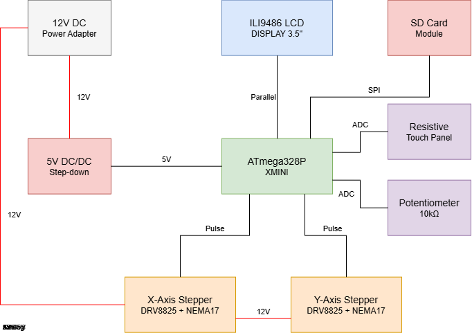
Mini-Plotter is an automated drawing system based on the ATmega328P-XMINI. The system operates as a closed-loop interface where user input is captured via a resistive touch screen or an SD card and translated into physical motion through two NEMA 17 stepper motors. The project logic is divided into three functional layers:
- Input Acquisition: Captures analog coordinates (via Resistive Touch) and menu selection (via Potentiometer) or digital data (via SD Card).
- Processing & Control: The MCU executes state-machine logic to handle three modes:
- Freehand
- Shape Correction (algorithmic smoothing)
- SD File Execution
- Output Execution: Real-time visual feedback on the ILI9486 LCD and high-precision motor control via DRV8825 drivers.
Block Diagram
Hardware Design
Component List
| Component | Specification | Role/Connection |
|---|---|---|
| ATmega328P-XMINI | 8-bit Microcontroller | Central processing and logic control |
| NEMA 17 Stepper | 1.8° Step Angle, High Torque | Dual-axis (X-Y) mechanical movement |
| DRV8825 Driver | Up to 1/32 microstepping | Current control for stepper motors |
| ILI9486 LCD Module | 3.5” TFT with Integrated SD Slot | UI display and data storage (SPI Interface) |
| Resistive Touch | 4-Wire Overlay | Coordinate input for manual drawing |
| Potentiometer | 10k Ohm Rotary | Menu navigation and mode selection |
| Power Supply | 12V DC / 2A | Powering motors and logic (via step-down) |
Assembly
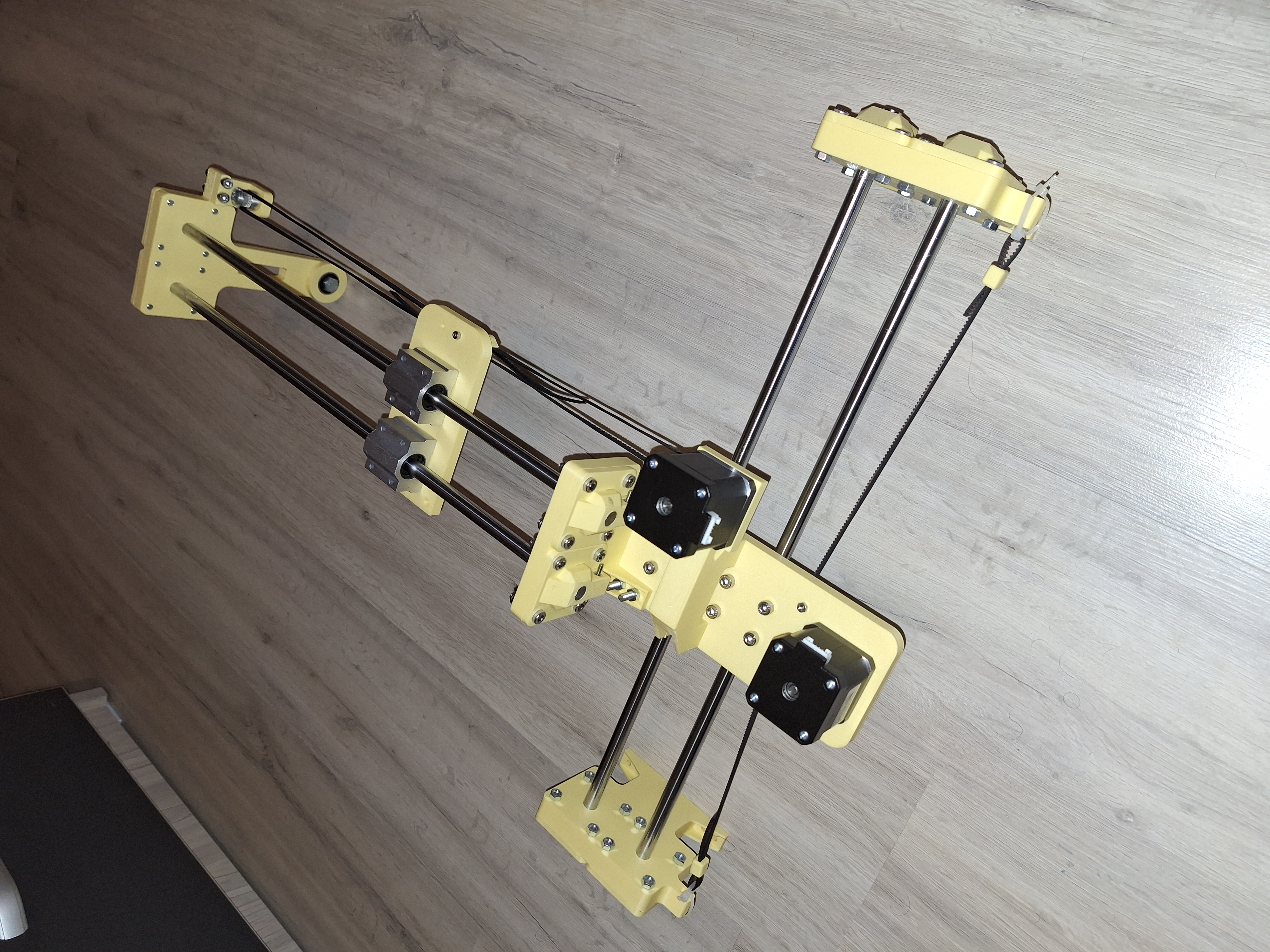
Hardware Implementation Status
The hardware architecture of the mini-plotter has been fully designed, verified, and mapped. The implementation is executed in two concurrent phases:
- Power and Motion Subsystems (Fully Implemented): The 12V to 5V DC/DC step-down regulation circuit, the dual DRV8825 stepper driver networks (including electrolytic noise-decoupling capacitors), and the NEMA 17 physical connections are completed and fully operational.
- Control and Display Interfaces (Schematic Level / Pending Integration): The 8-bit parallel LCD interface and SPI SD card slots are fully routed at the schematic level using optimized pin layouts to bypass the ATmega328P's IO limitations. Physical wiring of the display will follow the motion testing phase.
Pin Mapping & Justification
Due to the high number of peripherals required by this project (2 stepper drivers, an 8-bit parallel display, an SPI SD card reader, a touch panel, and a navigation potentiometer), the ATmega328P's pin map is utilized at 100% capacity.
To achieve this without using external multiplexers or IO expanders, several hardware-level optimizations were implemented:
| Component | Pin Name | MCU Pin | Type | Technical Justification |
|---|---|---|---|---|
| X-Axis Driver (A1) | STEP | PD2 | Digital Out | Dedicated hardware pin for step pulses. |
| DIR | PD3 | Digital Out | Direction control logic signal. | |
| Y-Axis Driver (A2) | STEP | PD4 | Digital Out | Dedicated hardware pin for step pulses. |
| DIR | PD5 | Digital Out | Direction control logic signal. | |
| SD Card Module | SD_SS | PB2 | Digital Out | Dedicated Slave Select line for SPI. |
| SD_DI (MOSI) | PB3 | Hardware SPI | Master Out Slave In - standard high-speed data line. | |
| SD_DO (MISO) | PB4 | Hardware SPI | Master In Slave Out - standard high-speed data line. | |
| SD_SCK | PB5 | Hardware SPI | Serial Clock line to synchronize data transfers. | |
| ILI9486 LCD (Control) | LCD_RST | PC4 | Digital Out | System reset line for the display controller. |
| LCD_CS | PC3 | Digital Out | Chip Select line for the parallel display bus. | |
| LCD_RS | PC2 | Digital Out | Register Select (Commands vs. Pixel Data). | |
| LCD_WR | PC1 | Digital Out | Write strobe signal clocking the 8-bit bus. | |
| LCD_RD | +5V | Hardwired | Optimization: Permanently tied to High. The MCU only writes data; reading from the display is disabled to save 1 digital GPIO pin. | |
| ILI9486 LCD (Data) | LCD_D0 - D1 | PD0 - PD1 | Parallel Bus | Lower 2 bits of the 8-bit data bus. |
| LCD_D2 - D3 | PD6 - PD7 | Parallel Bus | Middle bits of the 8-bit data bus. | |
| LCD_D4 - D5 | PB0 - PB1 | Parallel Bus | Higher bits of the 8-bit data bus. | |
| LCD_D6 - D7 | PC0 - PC5 | Parallel Bus | Remaining bits routing the full parallel byte. |
Electrical Schematic & Explanations
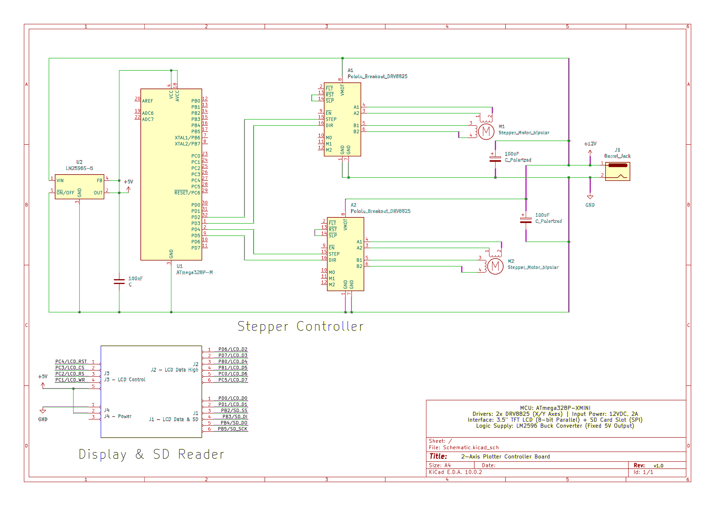
The circuit diagram is structurally grouped into three distinct functional blocks to isolate high-power inductive loads from sensitive logic electronics:
1. Power Supply and Voltage Regulation
The main system power is provided by an external 12V DC / 2A adapter connected through a DC Barrel Jack (J1).
- The 12V Rail powers the motor supply pins (`VMOT`) of both DRV8825 stepper drivers directly.
- An LM2596S-5 buck converter is deployed to regulate the 12V down to a stable 5V rail. This buck converter provides high efficiency under step-down conditions, preventing thermal issues.
- A 100nF ceramic capacitor is placed close to the microcontroller's `VCC` and `AVCC` pins to filter out high-frequency switching noise generated by the buck converter.
2. Stepper Controller Subsystem
Two Pololu DRV8825 breakout boards control the NEMA 17 stepper motors.
- Voltage Spike Protection: A 100µF electrolytic decoupling capacitor is placed in parallel across `VMOT` and `GND` right at the entrance of each driver board. Without these capacitors, the inductive energy/back-EMF from the motor coils could create destructive voltage spikes exceeding the driver's absolute maximum ratings.
- Driver Activation: The `RESET` and `SLEEP` pins of each driver are jumpered together locally to force the driver IC out of standby mode into an active state without wasting MCU control lines.
3. Display & SD Card Interface
The display block handles the routing for the 3.5” TFT LCD Shield. It separates the high-volume display pixel transfers onto an 8-bit parallel topology while routing the SD Card operations through the standardized hardware SPI pins (`MOSI`, `MISO`, `SCK`).
Hardware Assembly & Proof of Functionality
1. Physical Subsystem Assembly
The physical setup for the initial milestone focuses entirely on the core power distribution network and the dual-axis motion subsystem. The ATmega328P-XMINI development board is mounted alongside the custom-wired breakout board housing the two DRV8825 stepper drivers and the LM2596 buck converter module.
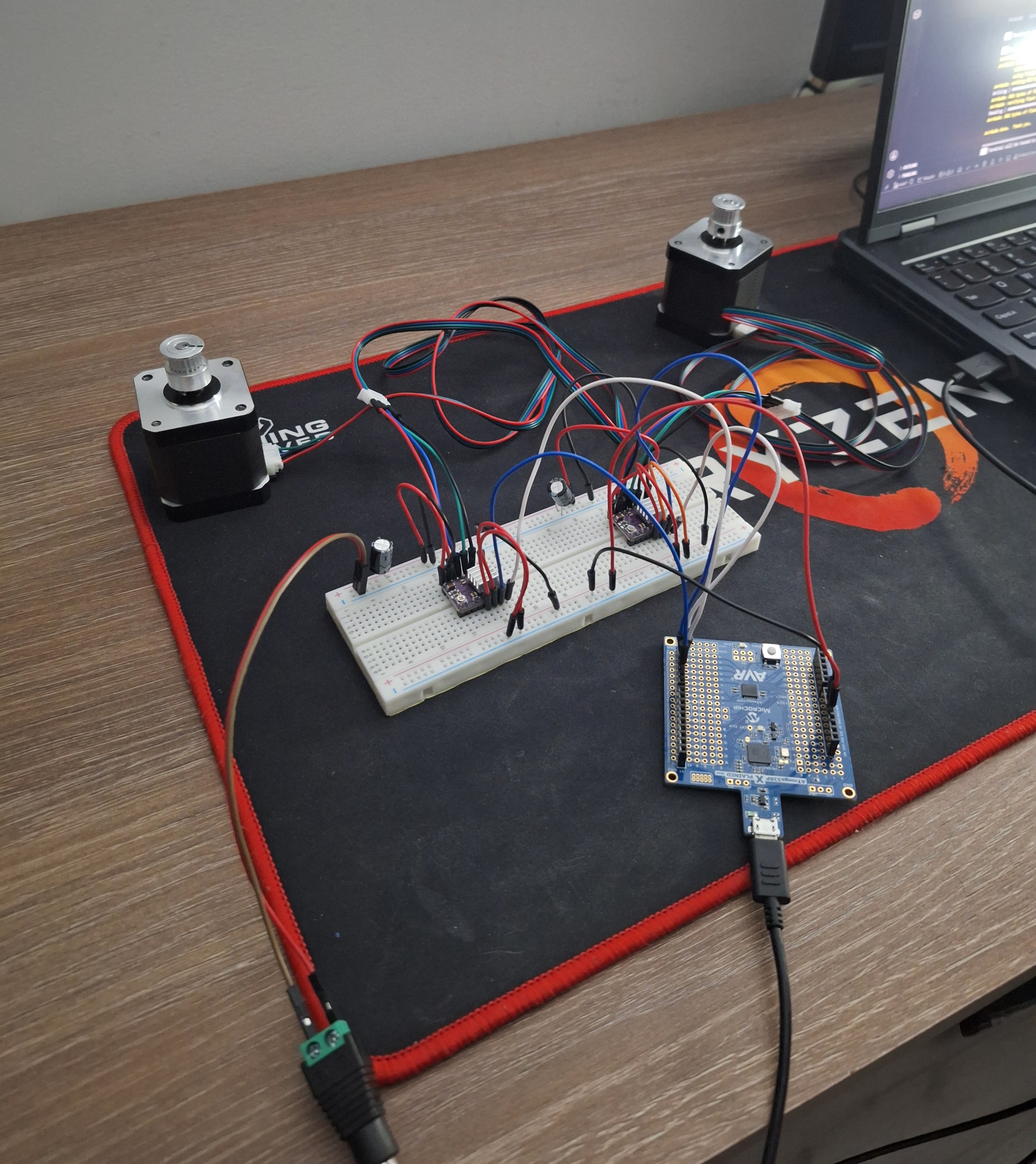
2. Diagnostic Testing Routine
To provide concrete validation of hardware functionality and signal integrity under heavy dynamic loads, a continuous firmware diagnostic routine was uploaded to the microcontroller. The routine commands both NEMA 17 stepper motors to cycle recursively through a strict directional pattern:
- Forward Phase: 3 complete revolutions clockwise (CW).
- Reverse Phase: 2 complete revolutions counter-clockwise (CCW).
- Execution Loop: The cycle repeats infinitely with a 500ms delay between directional shifts to test the system's transient response during abrupt current changes.
Given that the NEMA 17 motors feature a standard $1.8^\circ$ step angle (requiring 200 full steps per single $360^\circ$ rotation) and the DRV8825 pins M0-M2 are left floating (defaulting to full-step mode), the control script alternates precisely between sending a train of 600 pulses for the forward phase and 400 pulses for the reverse phase via the `STEP` pins (`PD2` and `PD4`).
3. Verification & Electrical Stability Analysis
The successful and continuous execution of this directional cycle validates several critical design factors of the current hardware revision:
- Transient Load Handling: The LM2596 buck converter successfully sustains a rock-solid 5V logic supply to the ATmega328P without resetting or browning out, even when the H-bridges inside both DRV8825 drivers switch inductive polarities simultaneously during the sudden 3-to-2 turn transitions.
- Voltage Ripple Attenuation: The local 100µF electrolytic decoupling capacitors placed at the `VMOT` pins effectively absorb the back-EMF energy spikes created when the motor coils change direction. This prevents any high-voltage feedback from degrading or permanently destroying the driver ICs.
- GPIO Control Integrity: The logical isolation between the step pulse generation loop and the shared ground planes is secure. The motors lock under full holding torque when idle and track angular steps flawlessly without stuttering, confirming high noise immunity across the control lines.
Software Design
1. Current Status of the Software Implementation
The software implementation is fully functional and successfully integrated with the hardware. The system is capable of initializing peripheral devices (TFT LCD, SD Card, Stepper Motors), processing user commands via a non-blocking UART interface, and executing physical movements by reading and parsing G-code (.GCO files) directly from the SD card. The entire kinetics engine operates asynchronously via hardware interrupts, ensuring highly precise and smooth 2D plotting.
2. Motivation for the Chosen Libraries
To ensure maximum performance and strict timing, standard Arduino libraries (such as Serial or Stepper.h) were intentionally avoided in favor of bare-metal AVR C++ programming. The only external third-party library used is:
- Petit FatFs (pff.h): Chosen for SD card filesystem access due to its exceptionally low RAM footprint compared to the standard Arduino SD library. It allows reading G-code line-by-line without exhausting the microcontroller's limited memory.
All other modules (UART, LCD rendering, and Stepper control) were written entirely from scratch using direct register manipulation (e.g., PORTA, TCCR1B) to maintain absolute control over CPU cycles.
3. Novelty of the Project
The defining novel element of this software architecture is the Custom Interrupt-Driven Kinetics Engine. In standard hobbyist plotters, stepper motors are driven using blocking delay loops (e.g., _delay_ms()), which paralyzes the microcontroller. In this project, the Bresenham Line Algorithm is deeply integrated into an AVR Hardware Timer Interrupt Service Routine (ISR). This allows the MCU to pulse the motors seamlessly in the background at exactly 4,000 Hz, while the main loop simultaneously parses complex G-code, updates the UI, and communicates over Serial without dropping a single physical step.
4. Utilization of Laboratory Functionalities
The project heavily applies concepts taught during the laboratory sessions:
- Hardware Timers & Interrupts: The 16-bit
Timer1is configured in CTC (Clear Timer on Compare Match) mode with a custom prescaler and compare match register (OCR1A = 499). This triggers anISR(TIMER1_COMPA_vect)exactly 4,000 times per second for high-resolution 1/16th Microstepping control. - USART (Serial Communication): Implemented bare-metal UART using
UBRR0,UCSR0A, andUDR0registers for a non-blocking 115200 baud command-line interface. - GPIO Manipulation: Fast pin toggling using direct port manipulation (
PORTA,PORTF) for maximum switching speed on the stepper direction/step pins and LCD data buses.
5. Project Architecture, Interaction, and Validation
The codebase is heavily decoupled and structured into independent C++ modules (stepper, uart, lcd, gcode, ui, sd_handler) interconnected through a shared globals state.
- Interaction: The primary infinite loop reads characters from UART and text lines from the SD card. When a coordinate is parsed by the
gcodemodule, it invokesmoveTo(). ThemoveTo()function calculates the discrete step vectors and safely loads them intovolatilememory. TheTimer1ISR then automatically takes over, converting those vectors into physical step pulses asynchronously. - Validation: The system was validated progressively. The UART command parser was tested via Serial Monitor for logic verification. The stepper kinetic logic was validated by ensuring no serial buffer overflow occurred during movement. Finally, overall system integration was proven by exporting an SVG file to G-code via CAM software and successfully observing the machine plot mathematically correct curves on paper without stuttering or crashing.
6. Finite State Machine (FSM) UI Implementation
To manage the user interface and system modes without blocking the main execution loop, a Finite State Machine (FSM) was implemented. The system operates in one of four distinct states at any given time, defined by an enum:
STATE_MAIN_MENUSTATE_SD_MENUSTATE_TOUCH_DRAWSTATE_HOME
The FSM is driven by the UART non-blocking parser. When a user issues a command (such as SELECT 1 or BACK), the parser acts as a state transition controller, updating the currentState variable and setting a needsRendering boolean flag. The primary infinite loop evaluates a switch(currentState) statement and routes execution to the appropriate module to redraw the TFT LCD.
This FSM architectural pattern is critical: it prevents the microcontroller from getting trapped in nested sub-menu loops. Because the state machine evaluates and exits rapidly, the main loop is free to continuously poll for new serial commands, read the SD card, and pass coordinates to the interrupt-driven kinetic engine simultaneously.
Bibliography/Resources
Stepper Motor Setup https://www.makerguides.com/drv8825-stepper-motor-driver-arduino-tutorial/
ILI9486 LCD + SD Reader Datasheet https://datasheet4u.com/datasheets/ILITEK/ILI9486/945603
FAT32 File System Module https://elm-chan.org/fsw/ff/00index_p.html
Github Project https://github.com/Hatmanul-RRC/ProiectPM-Plotter