Table of Contents
B.A.U.B.A.U.
Introduction
The problem with traditional password managers is that they are often cloud-based, which means you need to trust a third party with your sensitive information. The alternative is to use a local first password manager, and although there are some good options available, they can be difficult to properly set up and may not be as convenient to use, especially if you want to access your passwords on multiple devices.
One of the solutions to this problem is writing your passwords on a piece of paper and keeping it in a safe place, but we all know how that can end up.
But what if you could have a digital piece of paper? An encrypted piece of paper that only you can read? A device that lets you access your passwords with just a fingerprint, without the need for a master password or cloud storage? A device that can be easily carried around and used on multiple devices?
That's the idea behind B.A.U.B.A.U. (Biometric Authentication Unit & Bluetooth Accesss Utility), a local first password manager that uses biometric authentication to keep your passwords safe and, at the same time, easily accessible.
Description
Block Diagram
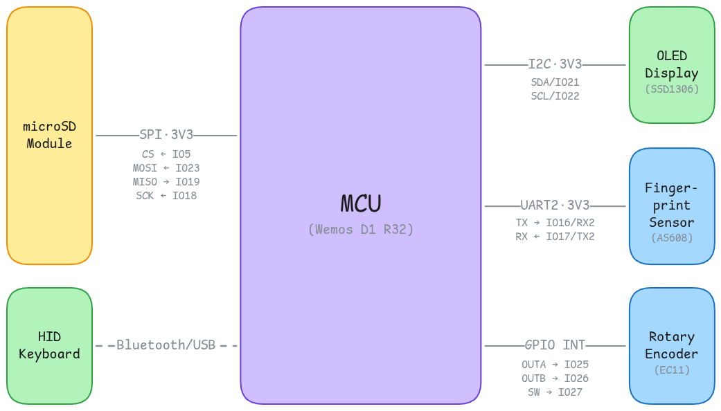
How do the components interact?
The main component of the system is the microcontroller. The Wemos D1 R32 (ESP32-based board) is responsible for orchestrating the entire system, handling user input, managing the display, and communicating with the fingerprint sensor and the microSD card module.
Here is what interfaces with the microcontroller:
- AS608 Optical Fingerprint Sensor: This sensor is used for biometric authentication. It captures the user's fingerprint and sends the data to the microcontroller for processing and verification. The communication between the microcontroller and the fingerprint sensor is done using a serial interface (UART).
- SSD1306 OLED Display: This display is used to show the user interface and the stored passwords. It communicates with the microcontroller using the I2C protocol.
- Rotary Encoder with Push Button: This component is used for user input, allowing the user to navigate through the menu and select options. The rotary encoder has two pins for the two signals (A and B) and a switch pin for the push button. Physical interaction with the rotary encoder generates interrupts that the microcontroller can detect and respond to accordingly.
- microSD Card Module: This module is used for storing the encrypted passwords on a microSD card. It communicates with the microcontroller using the SPI protocol.
Pin Selection
| Board Pin | Function | Component | Direction | Description |
|---|---|---|---|---|
GPIO16/U2_RX | UART RX | AS608 Optical Fingerprint Sensor | Input | Receives data from the fingerprint sensor. |
GPIO17/U2_TX | UART TX | AS608 Optical Fingerprint Sensor | Output | Sends data to the fingerprint sensor. |
GPIO21/SDA | I2C Data | SSD1306 OLED Display | Bidirectional | Used for data transfer between the microcontroller and the OLED display. |
GPIO22/SCL | I2C Clock | SSD1306 OLED Display | Output | Provides the clock signal for the I2C communication with the OLED display. |
GPIO25 | Rotary Encoder Signal A | Rotary Encoder with Push Button | Input | Receives the signal A from the rotary encoder. |
GPIO26 | Rotary Encoder Signal B | Rotary Encoder with Push Button | Input | Receives the signal B from the rotary encoder. |
GPIO14 | Rotary Encoder Push Button | Rotary Encoder with Push Button | Input | Receives the signal from the push button of the rotary encoder. |
GPIO5 | SPI CS | microSD Card Module | Output | Used to select the microSD card module for SPI communication. |
GPIO18 | SPI SCK | microSD Card Module | Output | Provides the clock signal for the SPI communication with the microSD card module. |
GPIO19 | SPI MISO | microSD Card Module | Input | Used for receiving data from the microSD card module to the microcontroller. |
GPIO23 | SPI MOSI | microSD Card Module | Output | Used for sending data from the microcontroller to the microSD card module. |
Hardware Design
Bill of Materials
| Componenent | Description | Procurement | Quantity | Datasheet |
|---|---|---|---|---|
| Wemos D1 R32 | A microcontroller board based on the ESP32 chip, used as the main processing unit for the password manager. | Sigmanortec | 1 | Datasheet |
| AS608 Optical Fingerprint Sensor | A biometric sensor used for fingerprint recognition to authenticate users. | Optimus Digital | 1 | Datasheet |
| OLED Display | A small display used to show information such as the stored passwords and user interface. | Sigmanortec | 1 | Datasheet |
| Rotary Encoder with Push Button | A rotary encoder used for navigation and selection in the user interface. | Sigmanortec | 1 | - |
| microSD Card Module | A module used for storing the encrypted passwords on a microSD card. | Sigmanortec | 1 | - |
| microSDHC Card | A storage device used for storing the encrypted passwords. | Any | 1 | - |
| 22 AWG Solid Wires | Used for connecting the components together. | - | Too many | - |
| Perfboard | A one-sided FR4 perfboard used for connecting the components. | - | 1 | - |
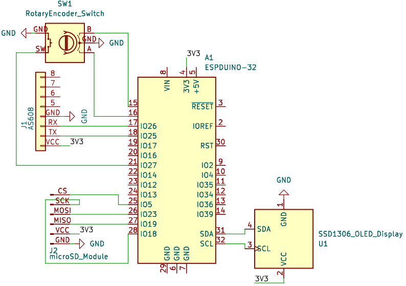
Schematic
Software Design
This project is developed using the PlatformIO environment, which provides a convenient and efficient way to manage the development process, including code editing, building, and uploading to the microcontroller.
In terms of libraries, we have no libraries.
Just kidding, at this moment, the project uses the following libraries:
adafruit/Adafruit SSD1306: A library for controlling the SSD1306 OLED display, providing functions for drawing graphics and displaying text on the screen.adafruit/Adafruit GFX Library: A graphics library for drawing shapes, text, and images on the OLED display.adafruit/Adafruit Fingerprint Sensor Library: A library used for interfacing with the AS608 Optical Fingerprint Sensor, providing functions for enrolling fingerprints, searching for matches, and managing the fingerprint database.- T-vK/ESP32-BLE-Keyboard: A library for HID keyboard over bluetooth
SD/FS(bundled with the ESP32 Arduino core): used to talk to the microSD card over SPI and read/write the vault file.mbedtls(also bundled with the ESP32 core): provides the AES-256 implementation used to encrypt the vault before it ever touches the card. No extra dependency needed, the ESP32 already ships with it.
Code Structure
The firmware is split into small, single-responsibility modules so it stays easy to navigate. Every module is a .h/.cpp pair under src/, and all of them pull their pins and tunables from a single config.h.
| Module | Responsibility |
|---|---|
main | The state machine (LOCKED > MENU > ENTRY) and the main loop that glues everything together. |
config | Every pin assignment, timeout and feature flag, in one place. |
logger | Tiny LOG/LOGF macros that compile to nothing when DEBUG_ENABLED is off. |
display | Everything that gets drawn on the OLED. |
encoder | Reads the rotary encoder and its button, debounced, as a single encoderPoll() snapshot per loop. |
fingerprint | Talks to the AS608 sensor: authenticates a finger, and enrolls/deletes templates for the admin menu. |
ble | Advertises the BLE keyboard and types out a password on the host device. |
store | The password store. Keeps the entries in RAM and persists them, encrypted, to the microSD card. |
admin | The on-device management menu: enroll/delete a fingerprint, delete an entry, wipe the vault. |
Every function and field is documented with Doxygen comments, so the headers double as the API reference.
Software Architecture
The whole device is a small state machine with one knob and one button, so it is worth describing exactly what each gesture does.
When idle, the device sits locked and asks for a finger. Scan an enrolled fingerprint and it unlocks into the menu, where turning the encoder browses the stored entries (the name in big letters, the account and a <current>/<total> position underneath).
From the menu you can:
- Tap an entry to open it. On the entry screen the password is shown masked (
********), you never see it on the display by accident (darn shoulder surfing). A quick tap types it on the paired device over Bluetooth (emulating a keyboard, works even on Apple devices); holding the button instead peeks the password, showing it in clear only for as long as you keep the button down. Turning the knob backs out to the menu. - Hold the button (a long press) to open the admin menu.
The admin menu is where everything that would normally need a computer happens, all on-device:
- Enroll finger: register a new fingerprint (two scans of the same finger).
- Delete finger: remove a stored fingerprint by id.
- Delete entry: drop a password entry from the vault.
- Wipe vault: erase every entry at once.
If there is no input for a while (AUTOLOCK_TIMEOUT, 30s by default), the device locks itself again.
Where the passwords live
The passwords never sit in plaintext on the card, duh. The store module keeps the entries in RAM (I know, not ideal) while the device is unlocked, and writes them out to a single encrypted file, /vault.dat, on the microSD card.
The file format is intentionally boring:
[16 bytes IV][4 bytes plaintext length][AES-256-CBC ciphertext...]
The entries are first flattened into a plain name<TAB>email<TAB>password line per entry, then encrypted as one block with AES-256-CBC using a fresh random IV on every save. On boot, storeBegin() mounts the card and decrypts the file straight back into the in-RAM vault. If the card is blank (no /vault.dat yet), it seeds a default set of entries and saves them, so a fresh card just works.
The AES key lives in the firmware (see STORE_KEY in config.h) rather than on the card, so popping the microSD into a reader gives you nothing but ciphertext. The known limitation is that the key is a build-time constant; a production build would move it into the ESP32's secure storage instead of source.
Tutorial
The whole interface is one knob you can turn (move), tap (select / send) and hold (admin menu / peek a password). In short:
- Unlock by resting an enrolled finger on the sensor.
- Turn to browse entries, tap one to send its password over Bluetooth (shown masked, never in clear).
- Hold on an entry to peek the password while you keep the button down.
- Hold in the menu to open the admin menu (enroll/delete a finger, delete an entry, wipe the vault).
First run: with no fingerprints enrolled the lock screen shows “Tap to set up”; tap, then open the admin menu and enroll your finger.
Results
Ended up with a working prototype that demonstrates the core features:
- Fingerprint authentication to unlock the device.
- Browsing stored password entries using the rotary encoder.
- Sending a password over Bluetooth by tapping an entry.
- Peeking a password by holding the button on an entry.
- An admin menu for enrolling/deleting fingerprints and managing entries.
- AES-encrypted vault stored on the microSD card, with a build-time constant key.
The fingerprint authentication is reasonably reliable, with a quick response time for unlocking. Confidence of the fingerprint match is printed to the serial console for debugging purposes, and in practice it seems to work well with the enrolled fingers.
To my surprise, but also obviously, the BLE typing works on all tested host devices (PC, Android and Apple). (well, it's just a standard HID keyboard, so it should).
Conclusions
Well, this was quite a wild ride.
Started off using a breadboard and jumper wires, quickly got a working proof of concept with the OLED, the encoder and the fingerprint sensor, tested each component, and as soon as I had everything working, I coded a simple state machine to glue it all together.
With everything working on the breadboard, I moved on to soldering it all together on a perfboard.
Here comes the fun part, I did the soldering immediately after getting it working on the breadboard.
I was obliviously working with the solder wire that my dad had lying around (spoiler alert: it was lead free) and with a soldering iron that was not very good. All I knew is that using more solder and lots of flux would help, so I ended up with a perfboard that looked like a crime scene, with solder blobs everywhere, but as per the multimeter, there were no shorts.
With the board looking like that, I wanted to remove the excess flux so I tried cleaning it with isopropyl alcohol.
That was a mistake and when I powered it on, the MCU would reset in a loop, and lo and behold, there was the magic smoke coming out from under the OLED.
Residue flux + isopropyl between many pins of the OLED and the MCU was causing shorts, and the OLED was fried.
That was the biggest setback, and such a lesson learned.
One OLED later, I started looking up how to properly do this and found out about leaded solder, which is much easier to work with, how to properly use a soldering iron, and about solid AWG wires for perfboard projects, so I ordered all the necessary materials and redid the whole thing with much better results.
Gotta say, this was the most fun I've had within this project, and I learned a lot about soldering and hardware assembly in general.
Last problem faced was that at the end, the OLED and the fingerprint sensor were not powering on and after hours of debugging with the multimeter, I found out that the pin header I used for the 3V3 line was not making good contact so I had to resort to some proper Romanian engineering.
Software wise, the project went pretty smoothly, I had a clear vision of how I wanted the interface to work and how the user would interact with it, so I just had to implement it.
Source Code & Resources
All sources live in this repository, organized into directories:
- assets/: block diagram, schematic and images.
- datasheets/: component datasheets.
- platformio.ini: board, framework and 3rd-party library dependencies.
Demo
Unlisted :)
Bibliography/Resources
Software
Hardware
- All the datasheets that are linked in the Bill of Materials section.
Both
- Anthropic's Claude for stupid questions.