Table of Contents
Electronic ball labyrinth game
Introduction
Functionality
The game features a ball and a labyrinth, controlled by a joystick using roll and pitch movements. It begins when the ball is placed at the start position. A timer is displayed on an LCD screen. The game is won when the ball reaches the end.
Purpose
The game features a ball navigating through a labyrinth, controlled via a joystick. The player uses roll and pitch movements to guide the ball from the start position to the end, with a timer tracking the progress.
Initial idea
I initially wanted to create a platform to self-balance a ball, but the complexity and time constraints led me to modify the idea. Instead, I combined it with the classic game of Ball in a Labyrinth.

Utility
This game can be used for entertainment, offering a simple yet challenging experience. It also brings a nostalgic element, reminding players of childhood games.
Description

I will use MG995 servo motors with mounting brackets to form the robotic arm that controls the maze. The servo at the bottom will control the roll movement, while the one at the top will control the pitch movement. These movements will be directed using a joystick. the button on the joystick makes servos return to their original, vertical position. To start the game, a button will be pressed, and the ball will be placed at the start position by the player. To end the game, another press on the button will make the game return to its initial state. The finish position will include a lever-type mechanical contact sensor to detect when the ball reaches it. A countdown timer showing the time left will be displayed on an LCD screen. Specific music will be played at different stages of the game: at the start, during gameplay, and at the end. The ending music will depend on the game’s outcome, playing a success song if the player completes the maze in time, or a failure song if time runs out.
Hardware Design
Components list
- Arduino UNO R3 ATmega328P, CH340G
- Speaker 40mm, 3W, 4Ohm
- LCD 1602 with I2C Interface
- Joystick module, 2 axes X Y
- 2 x ServoMotors MG995, 180 degrees, 11kg
- Contact sensor module, YL-99
- 4GB SD card
- DFplayer Mini
- 6V Ni-MH battery
- 1K1 resistor
- 2200 uF decoupling capacitor
- 1000 uF capacitor
- Power Bank
- Button
BOM
| Quantity | Name | Schematic | Purchase |
|---|---|---|---|
| 1 | Arduino UNO | U7 | Arduino UNO R3, ATMEGA328P, CH340G |
| 1 | LCD | U6 | LCD 1602 with I2C backpack |
| 1 | Button without retention | SW1 | PBS-110 |
| 1 | Speaker | SP1 | Speaker 3W 4Ohm |
| 1 | Joystick | S2 | Joystick 2 axes X Y |
| 2 | ServoMotor | U3, U4 | MG995 |
| 1 | Contact Sensor | SW2 | YL99 |
| 1 | Micro SD | - | micro SD 4GB |
| 1 | MP3 Player | U2 | DFR0299, DFPlayer Mini |
| 1 | Battery | U5 | 6V Ni-MH Battery |
| 1 | Resistor 1K1 | R1 | Resistor 1K1 |
| 1 | Electrolytic Capacitor | C2 | Electrolytic Capacitor 2200uF, 63V |
| 1 | Electrolytic Capacitor | C1 | Electrolytic Capacitor 1000uF, 25V |
Detailed Description
LCD 1602
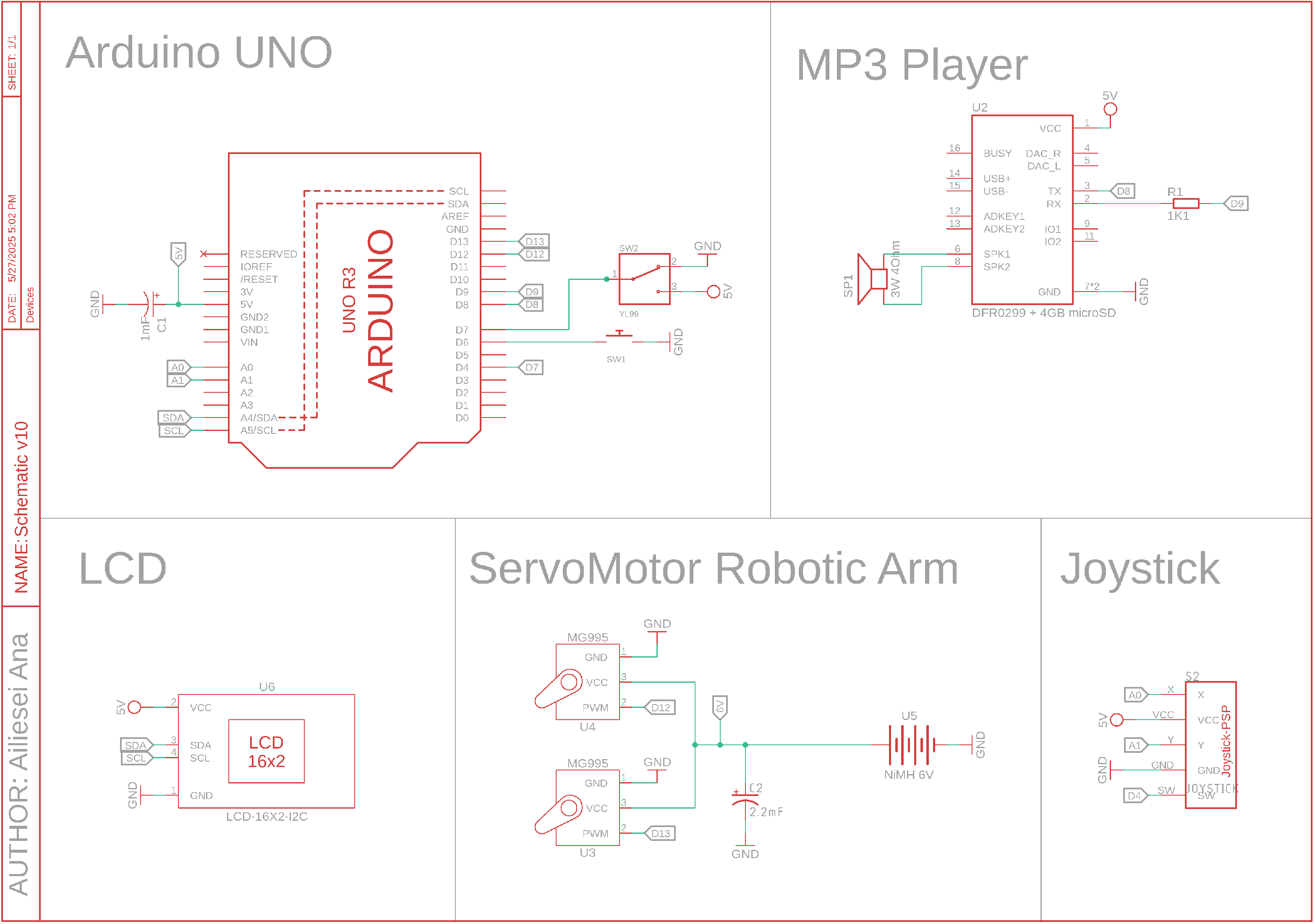
This LCD has an I2C backpack and will communicate with the Arduino trough the I2C interface. The pinout is at it follows
| LC2 1602, I2C PIN | Arduino PIN |
|---|---|
| VCC | 5V |
| GND | GND |
| SDA | A4 |
| SCL | A5 |
The A4 and A5 pins on Arduino are specifically made for communication trough I2C.
DFPlayer Mini
The MP3 player communicates with the Arduino via UART. It is connected to standard digital pins instead of the dedicated UART pins (U0 and U1), as those are used for USB communication with the laptop or power supply. I have to use pins 9 and 8 because the AltSoftSerial library uses those fixed pins. A 1K resistor is placed on the RX line to protect it from the 5V signal.
| DFPlayer Mini PIN | Arduino PIN | Speaker PIN |
|---|---|---|
| VCC | 5V | |
| GND | GND | |
| RX | D9 | |
| TX | D8 | |
| SPK1 | - | |
| SPK2 | + |
Joystick Module
The joystick module provides analog output, so it is connected to the Arduino’s analog input pins. The button has to be connected to a digital pin. The pinout is as follows:
| Joystick Module PIN | Arduino PIN |
|---|---|
| VCC | 5V |
| GND | GND |
| Rx | A0 |
| Ry | A1 |
| SW | D7 |
ServoMotors
The servomotors communicate with the Arduino via PWM, so they are connected to its PWM-capable pins. They are powered by a 6V, 2600mAh NiMH battery, as servomotors can draw high current—up to 2A under load—which the Arduino cannot supply. The battery supports a discharge current of up to 28A.
To reduce electrical noise, a 1000 µF electrolytic capacitor was added to help filter low-frequency noise, while two 47 nF ceramic capacitors were included to filter high-frequency noise.
The pinout is as follows:
| Joystick Module PIN | Arduino PIN | Battery PIN |
|---|---|---|
| VCC | 6V (+) | |
| GND | GND | - |
| PWM | D12/D13 |
Switches & Buttons
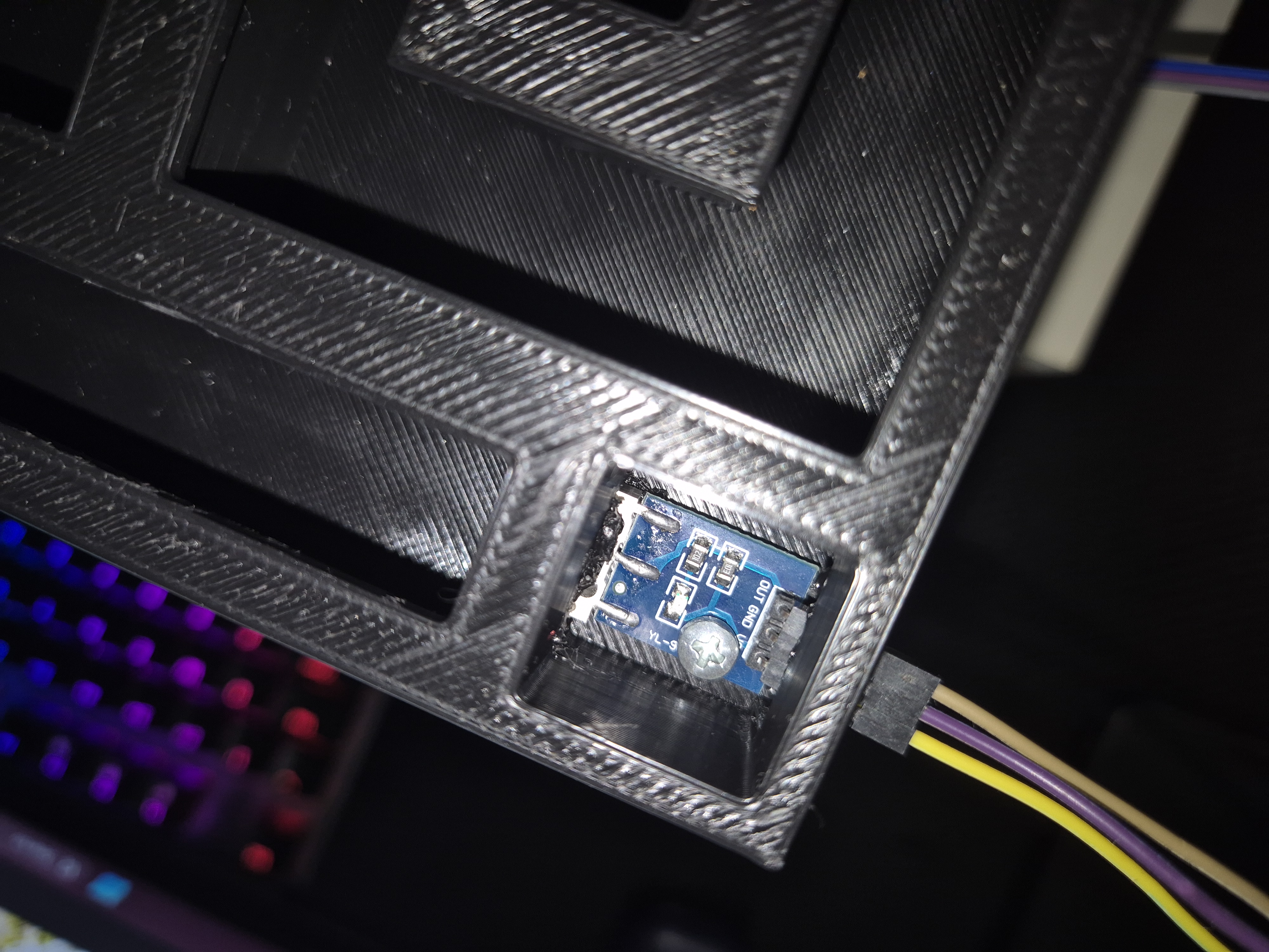
A contact-type mechanical lever microswitch is connected to a digital pin on the Arduino to detect when the ball has completed the maze. Additionally, a simple two-terminal push button is connected to another digital pin to start and end the game.
| Micro Switch PIN | Arduino PIN |
|---|---|
| VCC | 5V |
| GND | GND |
| OUT | D7 |
| Button PIN | Arduino PIN |
|---|---|
| 1 | D6 |
| 2 | GND |
Schematic
Connected Components Gallery
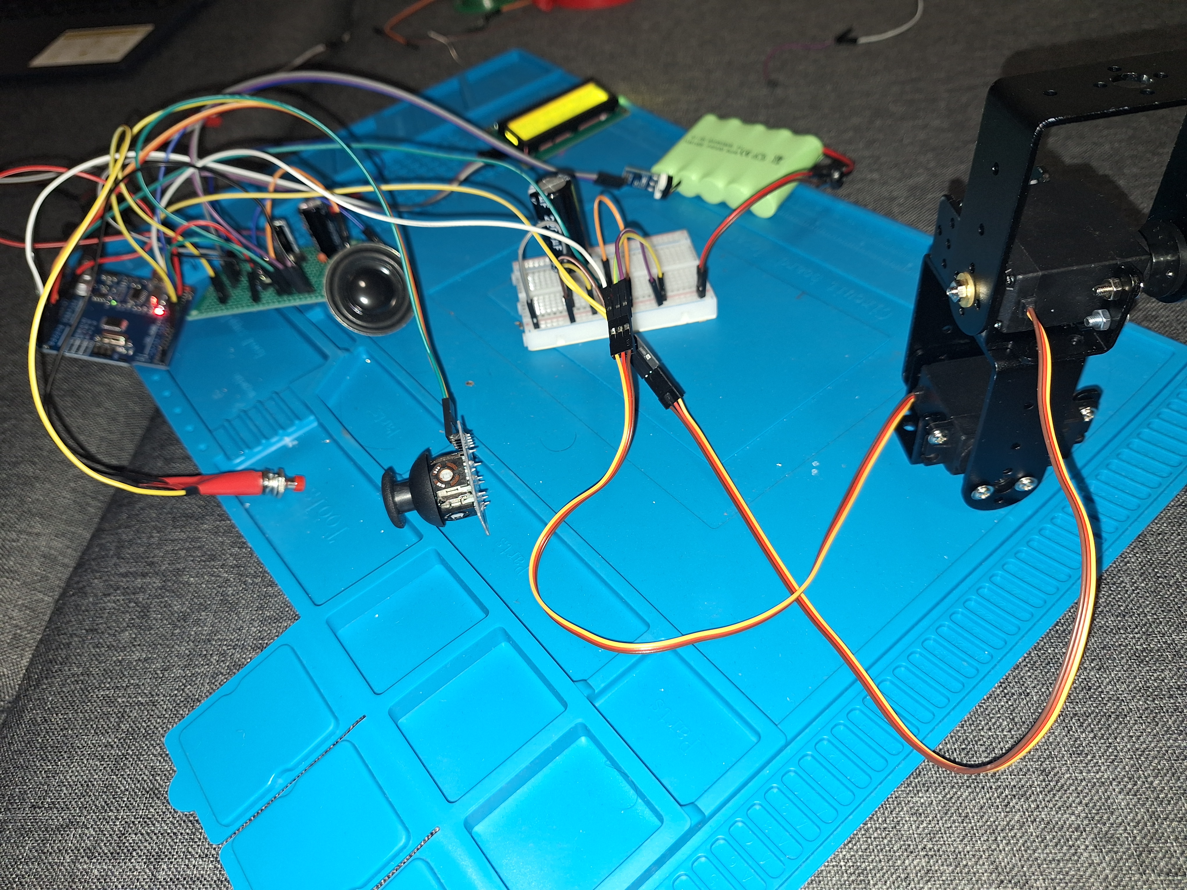 | 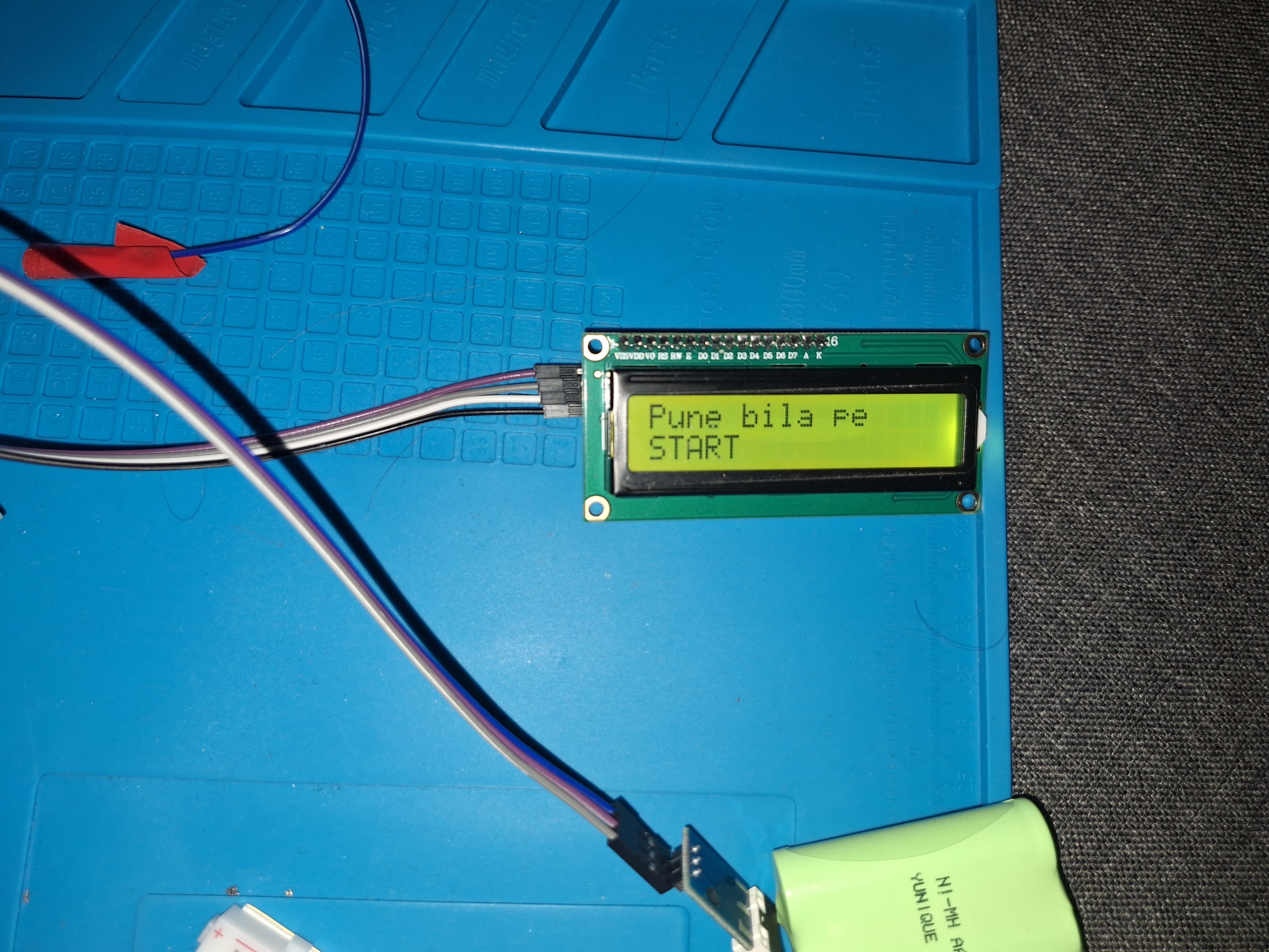 | 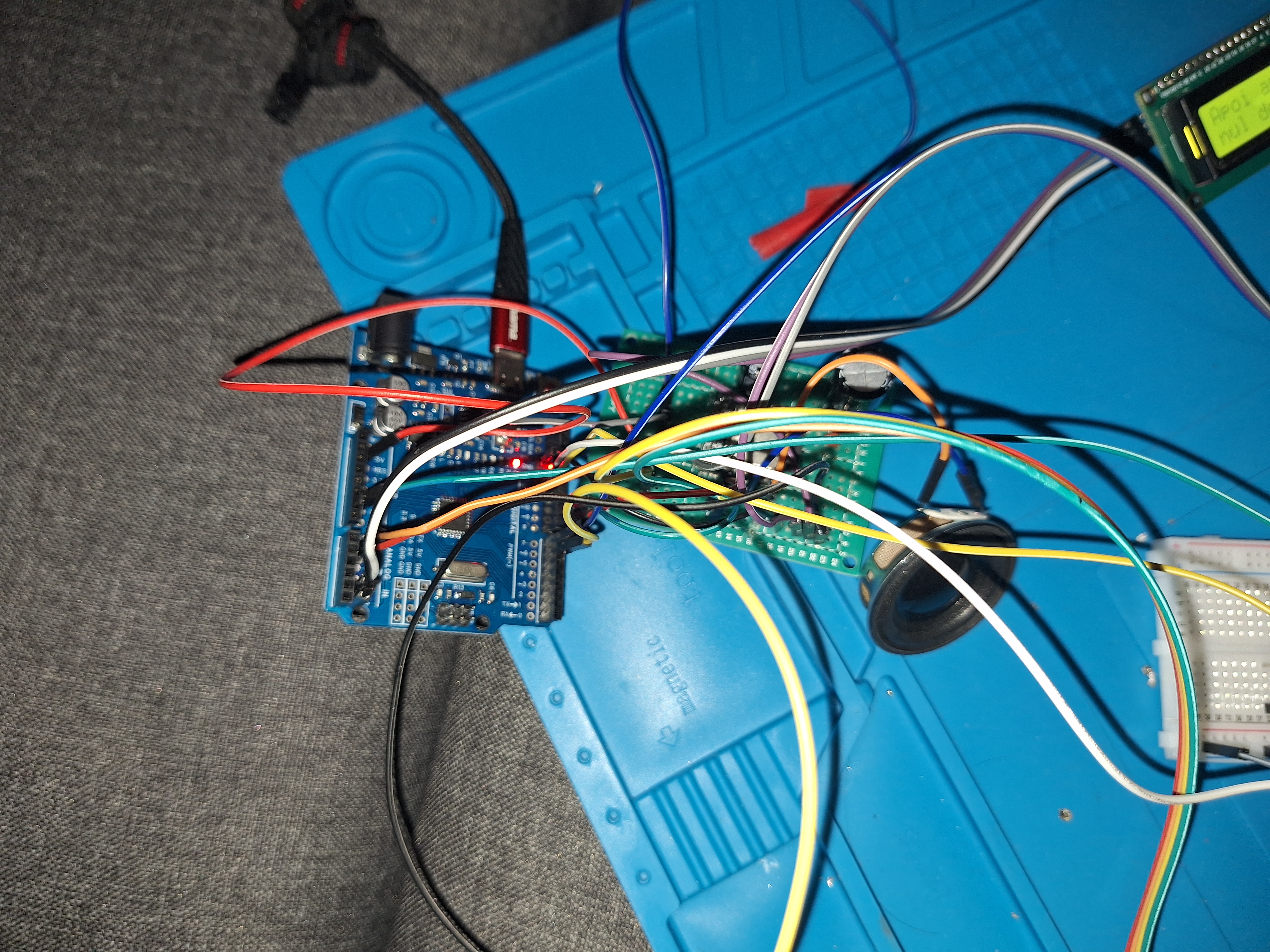 |
Proof components are working
In the video below you can see how the DFPlayer Mini behaves.
Software Design
Environment Used
I have used the Arduino IDE.
Libraries Used
- AltSoftSerial
- DFRobotDFPlayerMini
- ServoTimer2
- Wire
- stdio.h
AltSoftSerial & ServoTimer2
I used these libraries specifically because the standard SoftSerial and Servo libraries both use Timer1. Moreover, the standard SoftSerial disables the interrupt on Timer1, causing the servos to malfunction and behave erratically.
AltSoftSerial, on the other hand, works well because it does not disable interrupts on Timer1, and servos use Timer2 so there are no other conflicts.
Wire
I used the Wire library to implement my own I2C communication with the LCD.
Algorithms
I have implemented a state machine to handle the different states of the system. It has 6 possible states. Depending on the current state, a different music track is played and a different message is displayed on the LCD.
The game starts when the button is pressed. The game ends either by:
- Pressing the micro switch (winning), or
- Pressing the button again (restarting).
Example of state enumeration:
enum State {
  IDLE,
  COUNTING_START,
  PLAYING,
  LOST,
  WIN,
  WINNING_SONG_PLAYING
};
Game Flow
It starts in the IDLE state. The player must manually place the ball at the start position (marked with an S on the maze). When the button is pressed, the system enters the COUNTING_START state, where a “3-beep countdown” music plays and the LCD counts down from 3. During this state, the servos cannot be controlled yet.
Next, the system transitions to the PLAYING state. Here, the servos can be controlled via the joystick to navigate the maze. A pleasant music track plays, and the LCD counts down from 60 seconds. If the player wants to end the game early, they can press the button again, which stops the music and returns the servos to their default positions.
If the player continues, they must guide the ball through the maze until it reaches the final state. This is triggered when the ball activates a microswitch by pressing it with sufficient speed. Upon activation (WIN_STATE), a success melody plays (WINNING_SONG_PLAYING), the servos return to their original positions, and the game is won.
If the time runs out before the player reaches the end, the game is considered lost (LOST state). A losing melody plays, and the servos return to their original positions.
Functions
DFPlayer Mini
Initialize the DFPlayer:
void init_DFPlayer();
Handle states:
void handle_DFPlayer();
Buttons (Micro Switch & Start Button)
Button presses are handled using interrupts. Initialize the buttons (set them as INPUT and enable the internal PULL-UP resistor for the start button):
void init_Inputs();
Debounce the start button:
void debounce_button();
Handle micro switch press:
void handle_micro_switch();
LCD
I2C communication is implemented using the Wire library. Send half a byte (4 bits) to the LCD:
void lcd_send_half(uint8_t half, uint8_t rs);
Send a full byte to the LCD:
void lcd_send_byte(uint8_t byte, uint8_t rs);
Send a command to the LCD:
void lcd_command(uint8_t cmd);
Send a data byte to the LCD:
void lcd_data(uint8_t data);
Initialize the LCD in 4-bit mode:
void lcd_init();
Print a string on the LCD:
void lcd_print(const char* str);
Print two strings on the LCD — one on the top row and the other on the bottom:
void lcd_print_wrap(const char* str1, const char* str2);
Display two alternating 2-row messages on the LCD:
void lcd_print_alternating(int idx0, int idx1, const char* msg00, const char* msg01, const char* msg10, const char* msg11);
Convert a message index into a “time remaining” string:
char* index_to_time(int index, char* time);
Update the LCD based on the current system state:
void handle_lcd();
Servos & Joystick
The joystick button press is handled with an interrupt. Pressing the button makes the servos return to their initial vertical position. Converts a servo angle (in degrees) to the corresponding pulse width in microseconds.
inline uint16_t degToUs(int deg);
Checks if the value read from the joystick can be considered as the center default state (reading the default 0)
bool isZero(int val);
Handles servos based on joystick input
void handle_joystick_and_servos(unsigned long elapsed);
Initialize servos and bring them into the vertical position
void init_servo();
Implementation examples
I2C communication using Wire
Searching for the I2C address of the LCD:
Wire.begin();
  for (byte address = 1; address < 127; address++) {
    Wire.beginTransmission(address);
    if (Wire.endTransmission() == 0) {
      LCD_ADDR = address;
      break;
    }
  }
GPIO
Initializing the buttons:
DDRD &= ~(1 << buttonPin);
PORTD |= (1 << buttonPin);
DDRD &= ~(1 << leverPin);
DDRD &= ~(1 << joystickButtonPin);
PORTD |= (1 << joystickButtonPin);
Interrupts
Enable interrupts for the button, microswitch and joystick button.
PCICR |= (1 << PCIE2);     // Enable PCINT for PORTD
PCMSK2 |= (1 << PCINT22) | (1 << PCINT23) | (1 << PCINT20);  // Enable PD6 (PCINT22)
PCIFR |= (1 << PCIF2);     // Clear flag
sei();
Add the interrupt routine:
ISR(PCINT2_vect) {
  if ((!reading && PIND & (1 << buttonPin)) || (reading && !(PIND & (1 << buttonPin))))
    buttonPinInterrupt = true;
  else if ((!(PIND & (1 << leverPin)) && !leverState) || ((PIND & (1 << leverPin)) && leverState))
    leverPinInterrupt = true;
  else if ((!(PIND & (1 << joystickButtonPin)) && !joystickButtonState) || ((PIND & (1 << joystickButtonPin)) && joystickButtonState))
    joystickButtonPinInterrupt = true;
}
Documentation for the I2C communication with the LCD
Why those hex commands?
0x01 Clear Display, 0x02 Return Home, 0x06 Entry-Mode Set, 0x0C Display ON/OFF, 0x28 Function Set – their op-codes and bit-fields are listed in Table 6 “Instructions” of the datasheet.
The Function Set constant 0x28 is 0010 1000b ⇒ DL = 0 (4-bit), N = 1 (2-line), F = 0 (5×8 font). You must send this after forcing the controller into 4-bit mode so it knows the final interface width.
Power-up initialisation (Figure 24 flow)
0x30 -> 0x30 -> 0x30 -> 0x20
Send the “0x30 three times” handshake (still in 8-bit mode) and finally 0x20 to drop DL=0. This is the exact 4-bit initialisation sequence shown in Figure 24 “4-Bit Interface Initializing by Instruction” (under Initializing by Instruction).
4-bit write cycle (Figure 9)
In 4-bit mode each byte is split: high nibble first, low nibble second. Figure 9 labels the bus cycles:
| RS | R/W | Cycle name | Purpose |
| 0 | 0 | IR write | Latch a command or address into the Instruction Register |
| 1 | 1 | DR read | Fetch data from DDRAM/CGRAM via Data Register |
See Figure 9 “4-Bit Transfer Example” for the two Enable pulses per byte.
What the bit-flags in lcd_send_half() do
| Bit mask | PCF8574 pin → LCD | Why it’s set |
| 0xF0 | P4-P7 → DB4-DB7 | Carry the nibble you’re transmitting |
| 0x01 | P0 → RS | 0 = command, 1 = data (selects IR or DR) |
| 0x00 | P1 → R/W kept low | We only write; reads would need a separate read routine |
| 0x04 | P2 → E | Toggling E high→low latches the nibble; kept >450 ns with delayMicroseconds(2) |
| 0x08 | P3 → LED+ | Turns the backpack back-light on |
Mechanical Design
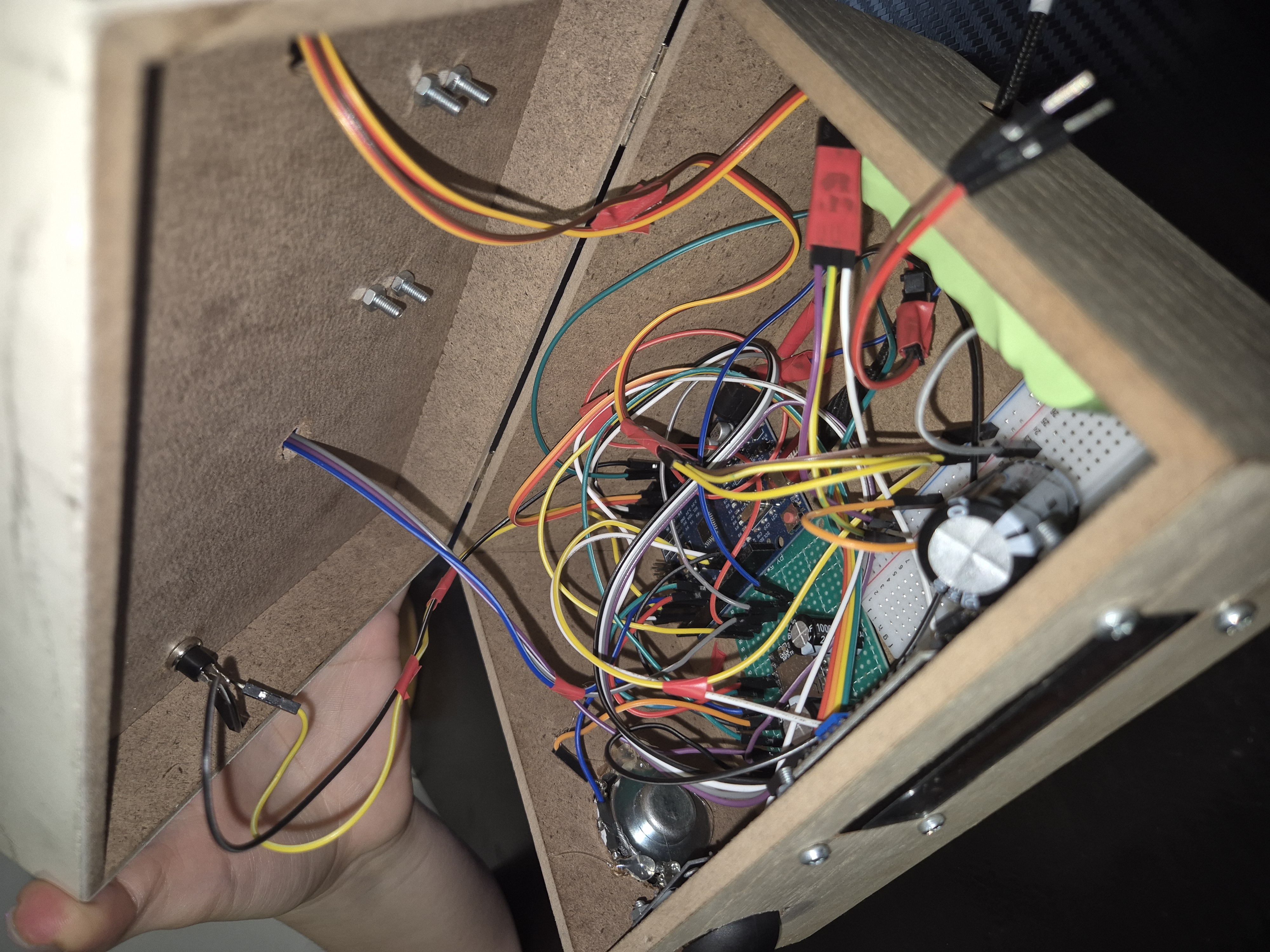
Physical Build
I used an MDF box as the enclosure for the project. I manually drilled holes for the joystick, LCD, speaker, button, USB cable, and necessary wiring. Additional holes were added to allow bolts to secure all the components and servos in place.
The robotic arm is constructed using two servos to control pitch and roll, mounted with two metal brackets. All electronics and wiring are neatly housed inside the box.
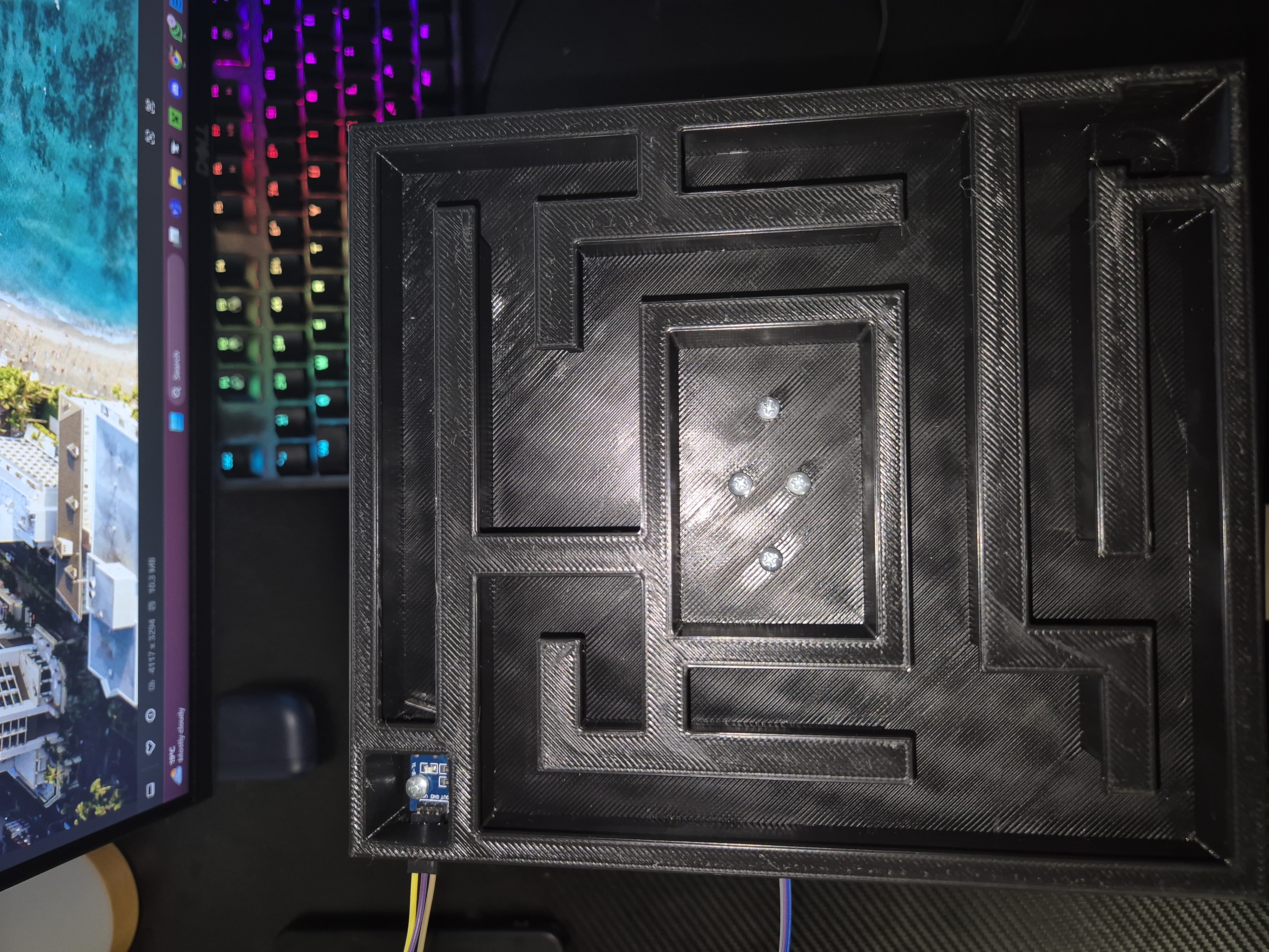
The labyrinth was 3D printed using Fusion 360. It includes pre-designed holes for bolts, allowing it to be securely attached to the servo brackets.
3D labyrinth photos
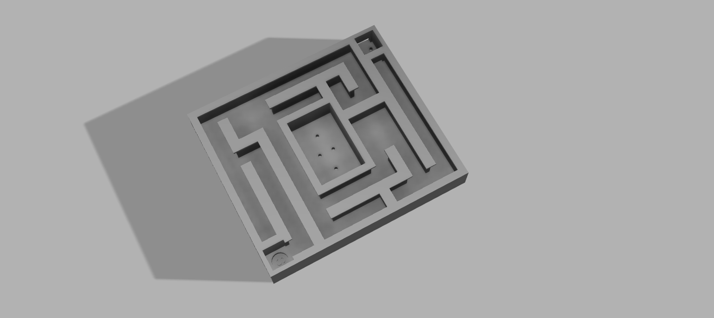 |  |
Box photos
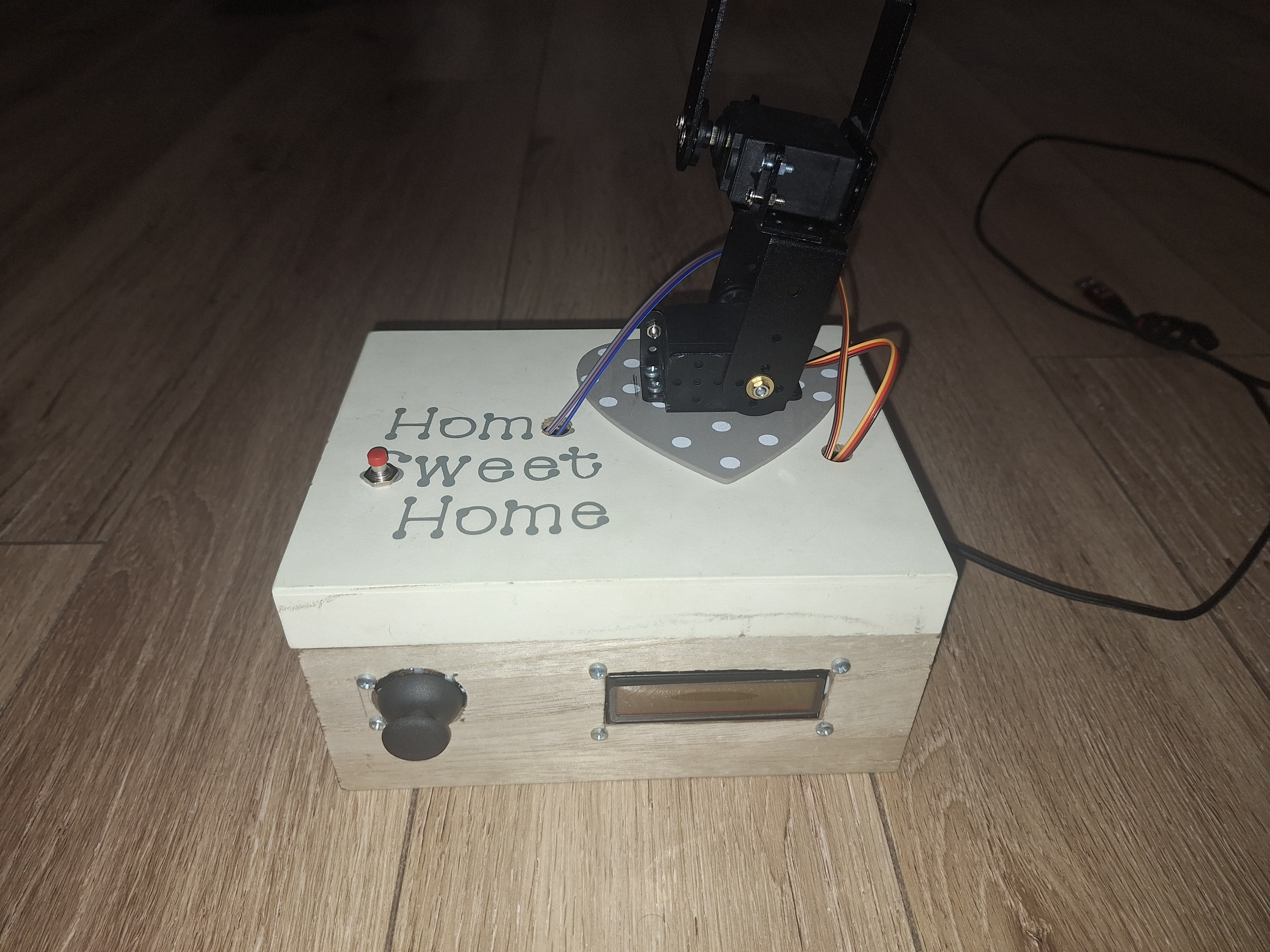 | 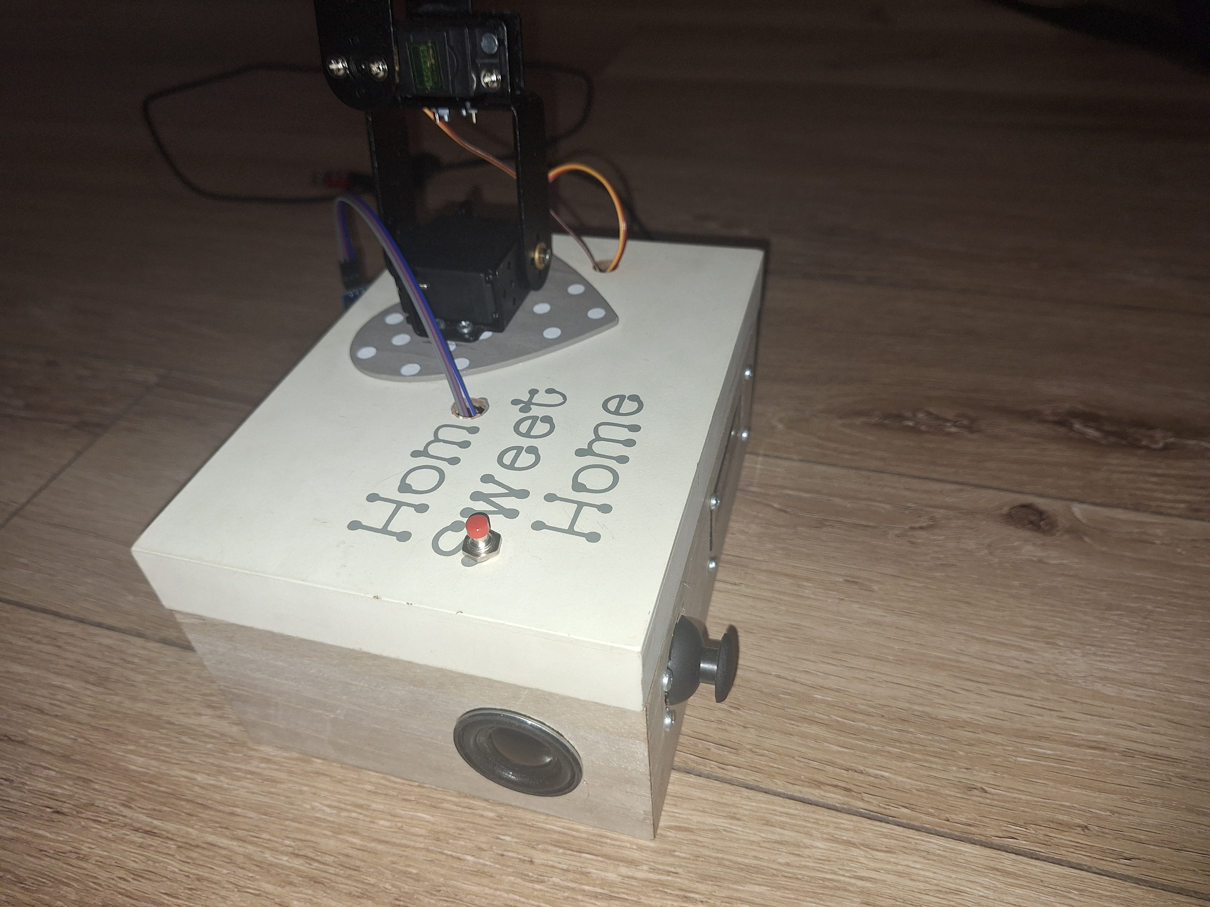 |
Results
Here are some final photos of my project:
 |  |
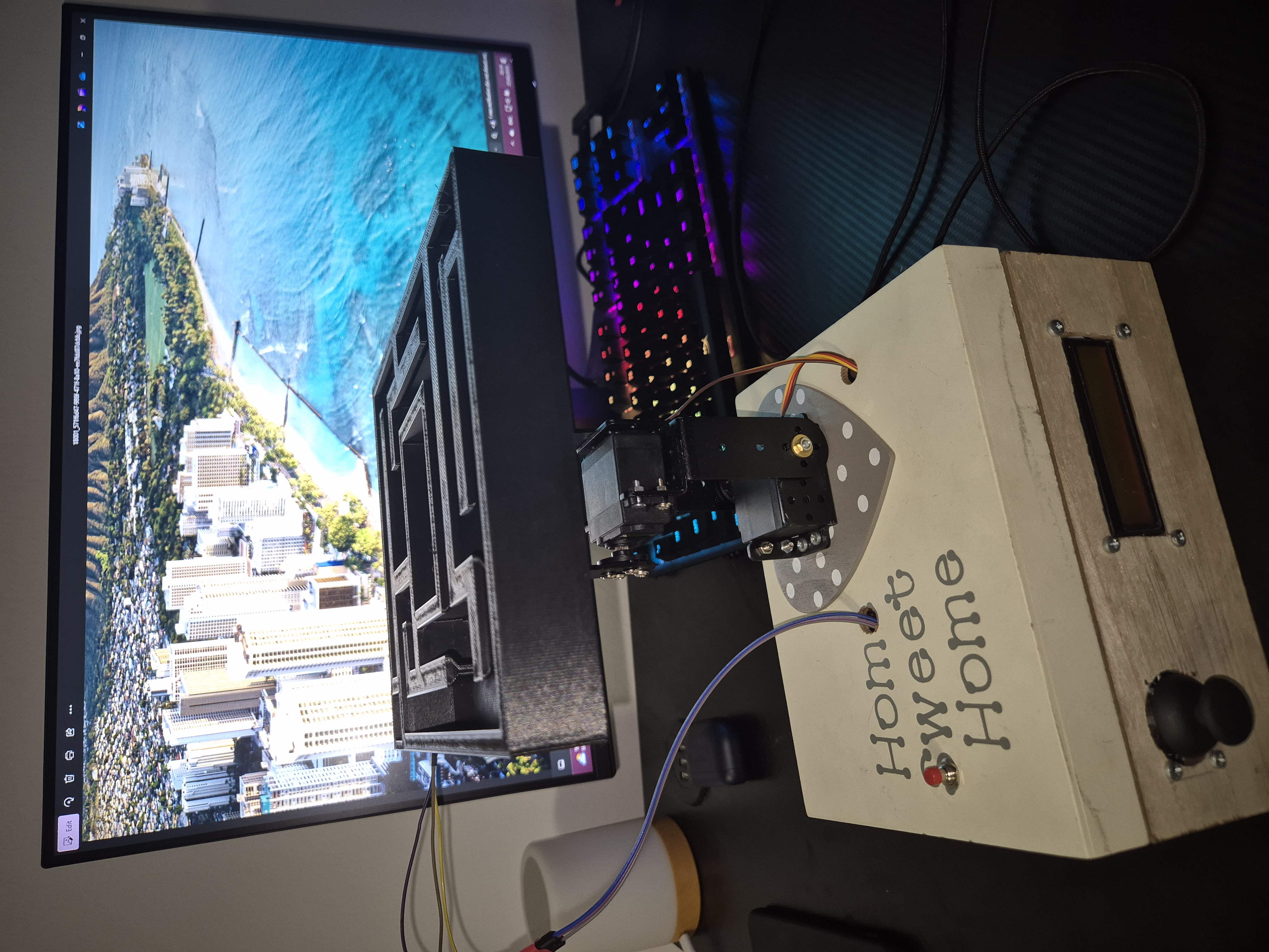 |  |
And here is a DEMO on how all the features work:
Download
You can download all files from my GitHub page: Electronic Ball Maze
- all.ino – The main file where I implemented all the software
- Schematic.sch – The schematic file
- labirint_v5.stl – The 3D model file of the labyrinth