Table of Contents
Theo Says
Introduction
- A game similar to Simon Says, but with lasers.
- Compared to Simon Says, when buttons light up in different patterns and the player has to replicate the sequence, this project moves a laser on a wall and the player moves a handheld laser to copy the sequence.
- The purpose of the project is to implement an innovative and fun game.
- I came up with this idea by thinking about what I can do with lasers and projecting one on the wall seemed natural. From there, I added the player component and linked it to the popular game Simon Says.
- In terms of utility, I believe it is a great way to relax after a long day at school or at work for everyone.
General Description
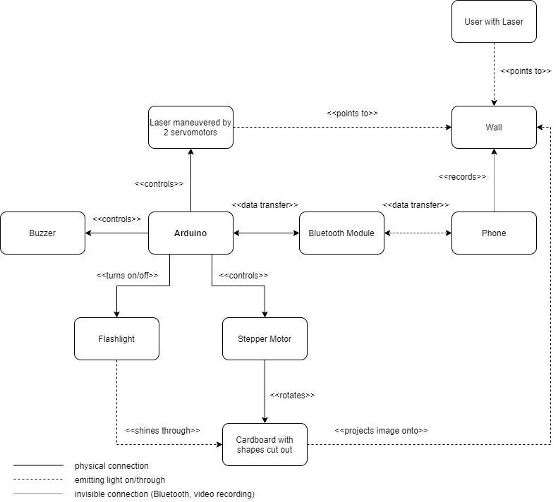
- Two servomotors control a laser module that projects the laser pointer onto a wall.
- The Arduino Board can choose to project the laser onto 4 points on the wall, the points forming a rectangle as big as the wall.
- The laser moves between those 4 points and can therefore have 8 possible directions: 2 vertical, 2 horizontal and 4 diagonal.
- When the game starts, the board generates a random point and valid direction, then projecting it.
- The player then has to mimic the same motion to advance using a handheld laser.
- Afterwards, the board generates a new valid move to append, the player then having to mimic the whole motion with the new addition.
- The game ends when the player makes a wrong move.
- When the player completes a sequence or makes a wrong move, an appropriate sound will be made.
- The validation is done by a mobile phone recording the wall and recognizing the movements, which are then sent to the Arduino Board via Bluetooth.
- When the game starts, the user makes a correct or wrong move, an image is projected on the wall using a flashlight. The light passes through a cardboard sheet with shapes cut such that they represent objects or text.
- The cardboard is rotated by a stepper motor behind it, allowing for multiple images to be projected.
Hardware Design
List of components:
- Arduino Due
- Servomotor S3003 x2
- Breadboard 830 points
- Laser Module KY-008
- Breadboard Power Supply 5V/3.3V
- Power Adapter 9V
- Bluetooth Module HC-06
- Passive Buzzer
- 28BYJ-48 Stepper Motor
- ULN2003 Stepper Motor Driver
- 5V Flashlight
- Various Wires, Resistors and Buttons
- Handheld Laser
- Mobile Device with a Camera
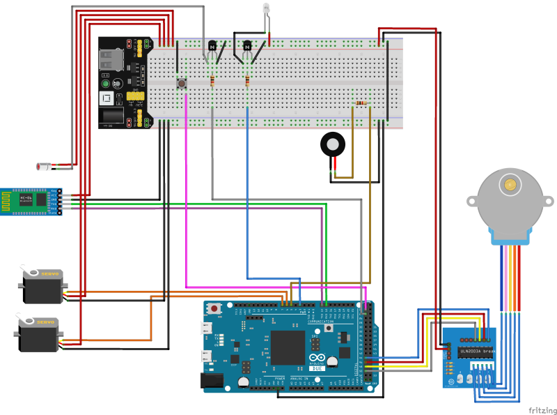
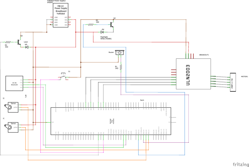
Higher quality diagrams are available on GitHub.
Software Design
Computer Vision
The first task implemented was the Computer Vision App. This started out as a project in Python, developed in PyCharm, which was fed video footage to analyze different scenarios. This was done to avoid having to deal with the inconsistencies introduced on mobile and to be able to review the results on a bigger display.
Finding the Laser Pointer
The final algorithm which recognizes the laser pointer directions first has to detect the pointer's position. This is done by filtering out all colors for which their respective HSV interpretations do not fall within specific margins. In other words, if a color falls outside a given range, then it is filtered out. Surprisingly, only the saturation and the value need to be considered, despite the fact that the laser is red. This is because the wall, in my setup, is quite dark compared to the laser pointer.
Next, on the mask resulted from the previous step, which contains 0 if the pixel was filtered out and 1 otherwise, we apply the OpenCV function 'findContours', which finds all blobs of unfiltered pixels. Usually, the only blob remaining is the pointer itself, whose position we store. If there are multiple contours detected, then, if we had detected a pointer during the previous frame, then we keep the contour closest to the previous one, otherwise we choose one at random. This heuristic assumes that the pointer is not moving too far during a single frame.
Tracking its directions
With the position determined, we add it to a queue with a fixed length (initialized with zeros at the beginning). This queue is part of a data structure which we will further call Tracker. The Tracker tracks the pointer's position and keeps track of various aspects about it. Once a position is added, the Tracker also adds to another queue the direction in which the pointer has moved. Therefore, we have a queue of the most recent directions in which the pointer has moved. The idea here is that the pointer moves in a direction if the most previous directions also face roughly the same way. This hints towards the standard deviation, which is a quantitative measurement for how different elements are. So the idea is to compute the mean of the most recent directions, which is the direction in which we are headed, and then the standard deviation, which indicates how certain we are that the laser is actually going in that direction. If the standard deviation is small, then we are fairly certain that the mean vector indicates where the pointer is going.
This idea needs to be fine-tuned in order to work. One problem is when the pointer moves very fast, let's say from one corner to another one in just 3 frames. This should register as a valid direction, but it will not, because the Tracker's history length is probably bigger than 3 and the other values inside will overpower these 3 big movements. The solution is to make those 3 movements weigh more. This is done by adding the restriction that all directions entered must have a length smaller than a threshold. If a direction exceeds that length, then it is cut uniformly with the minimum number of cuts such that each resulted segment's length is smaller than the threshold. Therefore, if those 3 big movements arrive, then they will not insert only 3 directions, they will insert many more, making the standard deviation very small.
Another problem is with the length of the directions. If there are several small directions processed by the Tracker, then it will have a small standard deviation even when the pointer is standing still and therefore should not register a valid gesture. The solution to this is applying a threshold to the length of the mean direction. If its length is smaller than a selected value, then we can assume that the pointer is standing still. Another problem with the lengths is when we have all recorded directions parallel, but of different lengths. This leads to a non-zero standard deviation, which is not desired, in this case. Therefore, we also keep a mean and standard deviation for the normalized directions, whose lengths are always 1, and this is the standard deviation which we check.
One more note in computing the mean and standard deviation: since we are constantly adding and removing directions in a queue-like fashion, we can use the rolling formulas for computing these values.
From here, we can check when we are confident that the pointer has moved in a given direction. Then we can use the 'atan2' function to determine the angle in which it is headed and from there determine whether it is moving to the left, top-left, top etc.
Calibration
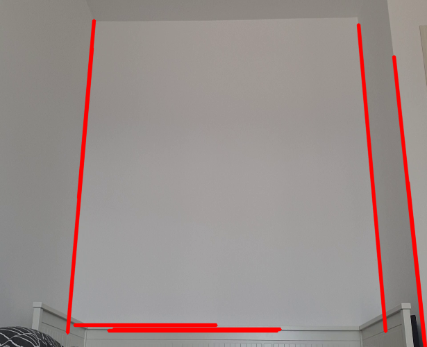
This approach is also problematic, because it depends on the orientation of the phone. To fix this, the wall used can be delimited by 4 corners and have the frame warped such that everything is projected on the wall itself, without relying on the orientation of the mobile device as much.
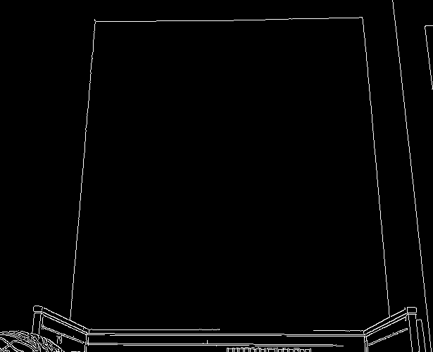
In order to do this calibration step, we first apply the Canny edge-detection filter on the given image, on which we then use the Probabilistic Hough Lines algorithm, both being provided by OpenCV. This algorithm detects the lines present in the image, which will be the 4 lines separating the wall. Since the simple Hough Lines algorithm is inefficient and we may be subject to noise when considering a single image, we use the probabilistic version, which does not detect all lines, but we do for a given duration. We only accept lines above a given length and keep the ones closest to the center, averaging them out as we scan.
Finally, when the calibration is done, the final line equations are calculated, the intersection points are determined and all further processing is done on the warped image.
After the Python application was completed, it was ported to Java and integrated into an Android application.
Arduino
The Arduino application was created to comply with the block diagram presented previously. The IDE used was Arduino IDE. There are several aspects which are worth mentioning:
Servo Dynamics and Calibration
The game needs the servomotors to follow specific motions prior to scanning the user input. Several problems occurred during tuning this feature. The servos were of poor quality and would often jitter and drift. One attempt to fix this was to modify the CV application and correct the servos' motions using this data and a PID controller. This was initially unsuccessful due to the limitations of the Bluetooth module, which had a poor bandwidth and latency, and the hysteresis on the servos. Perhaps this solution would have worked with stepper motors and a better Bluetooth module.
Despite that, what helped quite a lot was using the 'writeMicroseconds' function provided by the Servo Arduino library as opposed to the 'write' function. This offered much greater control and seemed to have reduced the drift by a small amount.
After careful consideration, I finally decided to include the PID controller in the project, but just as a calibration step prior to starting the game. After the phone calibrates, it starts sending the position of the laser pointer back to the board, which adjusts the servomotors' positions in order to match the required positions. The update rate is quite slow: one update per second, because 500ms of delay are introduced by the Bluetooth module and the servomotors do not move instantly. Tuning the controller was based on empirical data: the distance between two corners seemed constant on both axes, so the gain was set to this distance divided by the length of the wall in sensor space. Since the updates were so slow and the solution with only proportional gain was giving good results, there was no need to tune the integral and derivative terms, so they were set to 0.
Communication
The board communicates with the Android application via the Bluetooth module. While the module is meant to be used as a slave, in this application the Arduino is considered the master, sending commands to the mobile device and having the mobile device respond only to those requests. One such command is to start the calibration process, the mobile device later responding when it was completed. Also, the application can log the direction or position of the laser pointer, those logs being filtered by sending specific commands from the board, such as 'log_off' or 'log_direction'.
The Projector
The game ended up featuring a projector which works in the following way: a torch, which is connected to the Arduino, is seated on a stand and shines light towards a cardboard sheet, which contains various cuts signifying the frames displayed. The cardboard is rotated using a servomotor. The choice to use cardboard was made after it trying out with transparent Plexiglas only to discover that it was too heavy for the stepper to move. The cardboard is both lighter and easier to work with, even though it may not be as elegant. Also, the original design featured an LED using 220V. For my safety, I've decided to switch it with a 5V torch.
One unanticipated bug has to do with the torch, which has several modes of illuminating: normal and blinking. This leads to the torch switching modes after quick transitions. A possible optimization that can be done with the projector is having the stepper rotate during the sound effects or during the game-play.
The initial design featured a transparent LCD display, which was not used because I was unable to find one and the Nokia 5110 display did not work after the disassembly and reassembly.
Libraries Used
The libraries used on the Arduino board were:
- NewToneLib.h for controlling the buzzer
- Servo.h for controlling the servomotors
- HardwareSerial.h for communicating the Bluetooth module
- AccelStepper.h for controlling the stepper motor
Android Application
The application developed using Android Studio contains a port of the computer vision algorithm described previously and also features to handle communication with the board. The application plays the role of slave in this context, being used as a separate camera module rather than a mobile device with higher computing capabilities. Because of the low resources on the Arduino, the messaging rate was limited by the application.
Results
The application was completely implemented and the only shortcomings left that I could find were:
- Poor servo precision
- The projector not being visible enough during daytime
- The computer vision algorithm not working well enough during nighttime
Despite that, overall the project was a success and here is the video presentation: https://youtu.be/tnsvUFoqALQ
Conclusions
I enjoyed working on this project and have learnt so much from it. This was my first project which involved computer vision and I am happy to have combined this field with a physical project. I have learnt a lot about servomotors, buzzers and their imperfections and how to address them, but also about the ARM architecture, working with different voltage levels and how important good libraries are. This project has allowed me to be more creative and for that I am thankful.
Download
The source code and higher quality diagrams are available here: https://github.com/zdavid112z/Theo-Says
Journal
- 3-9 May
- Connecting the servomotors and having basic gestures displayed
- Computer Vision app in Python
- 10-16 May
- Researching the projector and finding adequate parts
- Improving the CV app
- 17-23 May
- Finalizing the CV app and porting it to Android
- Connecting the Android app to Arduino
- Creating the buzzer sound effects
- Building the projector and integrating it into the project
- Designing and implementing the gameplay
- 24-30 May
- Testing the PID controller on the servomotors
- Bug-fixing
- 31 May - 4 June
- Implementing the PID controller for servo calibration
- Fixing the buzzer bad sound effects using the NewToneLib library
