Table of Contents
Streams nodes
Run
The nodes which will start the payload. This is practically the first data flow sent towards the rest of the nodes you use in an application.
In its settings you have three fields.
If no payload is specified the payload is set to the current time in milliseconds since 1970. This allows subsequent functions to perform time based actions. You can write it yourself if you chose for it to be a string.
The topic field can hold data to be used later, in other functions.
The repeat function does what it says on the tin and continuously sends the payload every x seconds.
The Fire once at start option actually waits 50mS before firing to give other nodes a chance to instantiate properly.
The print node can be connected to the output of any node. It will display msg.payload field of any messages it receives.
The button to the right of the node will toggle it's output on and off so you can de-clutter the console window.
If the payload is an object it will be converted to String first for display and indicate that by saying ”(Object) ”.
By connecting the two blocks you send the output of run as input for print.

Functions
Function
A function block where you can write code to do many other interesting things.
By convention it will have a msg.payload property containing the body of the message.
If you double click on it, you will find the name field, the second field, where you write the code and the last one, where you specify how many outputs the node has.
 For this node you can find an usage example in Course 3: Software for the Internet of Things .
Visual
This node is similar to the function block, only that the second field will consist of visual blocks.
Look up an example in Lab. 03 - Blink an LED .
Delay
Introduces a delay into a flow or rate limited messages.
Default delay is 5 seconds and rate limit of 1 msg/second, but both can be configured.

The delay node is placed in an example in Course 3: Software for the Internet of Things as well.
Switch
A function node which will evaluate the message received and pass it on after filtering it though a set of ruled. You can create the rules in the node's settings.
 Find an example of how to use the node in Course 3: Software for the Internet of Things .
Social: Send and receive
You can make boards communicate. The message that they exchange will be in the payload.
The Send node needs the label, which is the identification of the expected message. It should be the same one in the receive message node.
 The third field asks for the board ID. In send you need the receiver board ID. To obtain it, go to the main page, find your board and, in its options, choose Board ID

Here's a simple and short example on a situation where you might need this very nodes. The temperature from a room is needed. The user who has these values wants to send them to your board, for you to insert them in your own project. The first user needs a Send message node, a label he decides over and your board ID. He will take the values from the temperature sensor connected, say on pin A0 and include them in the message to be sent.
You, on the other hand, will have to put a Receive message node which, in this example, will print on your console the values respective to the temperature, in an analog range (0 - 1024) every time it gets a message from the first board.


Say
You can make the board speak. Just insert this node and specify the message and the language. It will be saved in the payload.

For instance, a possible application would implement this block and two other simple ones: the run node and a change node, where you write the message you expect from your project.
I/O pins
- digitalWrite - it will write 0 or 1 on a digital pin, the one that you choose in the settings.
- digitalRead- reads 0 or 1 from a digital pin demanded in its settings and saves this value in the payload.
- analogWrite - reads the value from the analog pin mentioned in the settings
- analogRead - writes a value on an analog/ PMM pin. Said value will be in the payload.
 For these nodes you can find examples in Course 3: Software for the Internet of Things
- Shift in/ out- When it receives an input, shifts in/out a byte value from a pin using the clock pin as a clock. The value read/written is in payload. If no data pin is specified, the pin number is the topic field of the message.
 Here's an example on how to use the shift out node. You want to light up 3 LEDs one by one, without changing the state of the previous one. Picture this: you have the pins connected to 3 consecutive pins of a shift register so, you want to have on them the values: 0, 0, 0 when they are all out; 0, 0, 1 when the last pin is high; 0, 1, 1 when the last two are turned on and for all the LEDs to be alight 1, 1, 1. The corresponding values would be 0, 1, 3 and 7 which, in binary, would look exactly like the values you expect. Make a function which returns these numbers and the shift out node will write on the shift register exactly what you need. Make sure the data and the clock pin correspond to the shift register's pins.
 The easiest way to do this is to select, in the run node, the Times option, instead of timestamp. This will send in the payload a number, starting with 0, which is incresing by one each time a new message is sent out. The function should look like this.

Signals
- receiveSignal- puts in the payload the value received though the signal, from the dashboard. Write in the settings the name of the signal you expect, which should be identical with the one in the dashboard.
- sendSignal- sends the value of the payload to the signal with the same name in the dashboard or to a certain number of boards.
 Find examples of how the send signal node works in Lab 05. Connecting Analog Sensors to the board and adding charts .
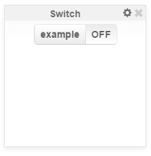
As for the receive signal node, you add a swith in the dashboard and name the signal it sends in a paticular way.
Afterwords, you come back to your main page and add a receive signal node. This one will start the project when it gets the message sent from the switch, and will put in the payload the value 0 or 1, depending on the switch's state. You can use this value to light up an LED, for example.


Web servers
- http request - this block can either get, post, pull, delete the data from a web page depending on what method you choose
- Web route - will start a web server which listens on the port you choose and has a method for the configured route
- Web response- it will set the response of the server. In status you configure it. Default is 200 which is page found.
All the additional information you need can be found in Course 09. Web servers and examples in Lab 08. Web services .


